A.2.8 depth 12 interleaver/de˚interleaver, A.2.8 depth 12 interleaver/de-interleaver, Figure a-18. interleaver/de-interleaver – Comtech EF Data SDM-9000 User Manual
Page 209
SDM-9000 Satellite Modem
Options
Rev. 4
A–23
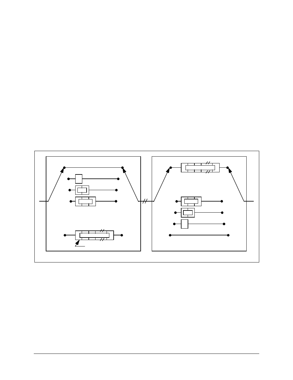
A.2.8 Depth 12 Interleaver/De-interleaver
Conceptually, the interleaver is composed of I = 12 branches, cyclically connected to the
input byte stream by the input switch. Each branch is a FIFO shift register, with
depth = 17 x branch index. The cells of the FIFO contain 1 byte, and the input and output
branches are synchronized. For synchronization purposes, the sync bytes and inverted
sync bytes are always routed in branch 0 of the interleaver, corresponding to a null delay.
The de-interleaver is similar in principle to the interleaver, but the branch indexes are
reversed (i.e., branch 0 corresponds to the longest delay). De-interleaver synchronization
is accomplished by routing the first recognized sync byte to branch 0.
Figure A-18 shows the interleaver/de-interleaver block diagram.
17
17x2
17x3
17x11
0
1
2
3
11
0
1
2
3
11
17x11
0
0
17x3
8
8
17x2
9
9
17
10
10
11
11
•
•
•
•
•
•
INTERLEAVER
SYNC BYTE ROUTE
DE-INTERLEAVER
17 BYTE FIFO SHIFT REGISTER
SYNC BYTE ROUTE
Figure A-18. Interleaver/De-interleaver