2 modulator, 1 description, 2 modulator 5.2.1 description – Comtech EF Data SDM-9000 User Manual
Page 132

Theory of Operation
SDM-9000 Satellite Modem
5–4
Rev. 4
5.2 Modulator
5.2.1 Description
The modulator PCB fits in the top slot of the modem chassis. The card provides a
modulated carrier of 50 to 180 MHz from the interface PCB digital data stream. The
types of modulation performed on the transmitted baseband data are:
•
QPSK
•
8PSK (optional)
•
16QAM (optional)
The optional 8PSK and 16QAM modulation provide increased bandwidth efficiency
over that of the standard QPSK. Refer to Section 5.6 for a description of the modulation
types.
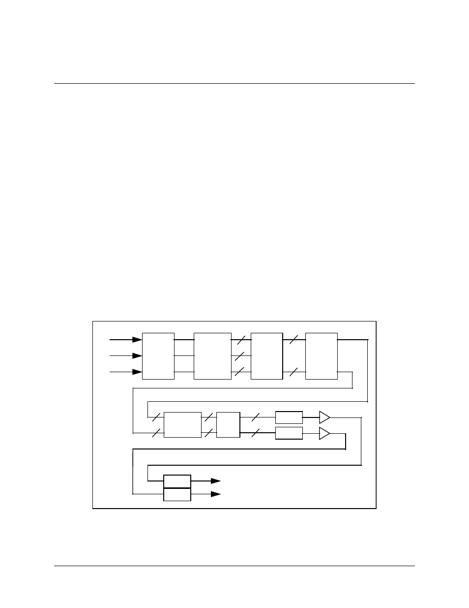
Figure 3-2 shows the modulator PCB. A block diagram of the modulator baseband
section is shown in Figure 5-2, and the modulator RF section in Figure 5-3. All
modulator jumper settings are listed in Table 3-2.
DIFFERENTIAL
ENCODER
CONVOLUTIONAL
ENCODER
PUNCTURE
LOGIC
PARALLEL
TO
SERIAL MUX
VECTOR
MAPPING
CW
TEST
MODES
DIGITAL
EQUALIZER
DIGITAL
EQUALIZER
NYQUIST
FILTER
NYQUIST
FILTER
I BASEBAND
OUTPUT
Q BASEBAND
OUTPUT
TX DATA
D0
D1
D2
2
2
2
2
2
2
2
Figure 5-2. Modulator Baseband Section Block Diagram
