5 main and extension frame power connections, 6 remote start of 8400 psu, 5 main and extension frame power – Cadac R-Type User Manual
Page 23: Connections
3-9
Revision R2005-2
R-Type
61618
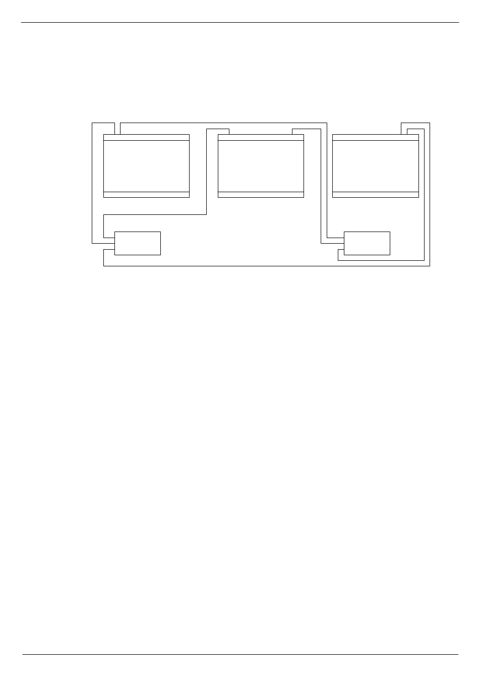
0DLQ#DQG#H[WHQVLRQ#IUDPH#SRZHU#FRQQHFWLRQV
See fig 1-4 below for schematics of the frames power connections.
1.
Connect a PSU cable between the “SYSTEM 1" rack and the “PSU SYSTEM 1"
connector on the MAIN FRAME.
2.
Connect a PSU cable between the “SYSTEM 2" rack and the “PSU SYSTEM 2"
connector on the MAIN FRAME.
3.
Connect a PSU cable between the “SYSTEM 1" rack and the “PSU SYSTEM 1"
connector on the EXTENSION FRAME 1.
4.
Connect a PSU cable between the “SYSTEM 2" rack and the “PSU SYSTEM 2"
connector on the EXTENSION FRAME 1.
5.
Repeat procedures 3 and 4 for EXTENSION FRAME 2 (a 3 frame console).
The 8400 also provide a 4th output connector for linking a 4th frame into the system.
61619
5HPRWH#VWDUW#RI#;733#368
Each 8400 switch-mode power supply provides the following outputs: 13v, ±18v and
48v. Each PSU is fitted with a front panel mounted 9-way 'D-type’ connector labelled
‘Connections for Remote Start’. If a remote start facility is used, Power Failure and
Over-Temperature LEDs may also be fitted with the remote start switches if required.
Fig 3-15 shows the circuit for starting up a “system” with a single switch. This has
proved to be the most popular method of connecting the remote start facility. This cir-
cuit can easily be extended to provide a single switch remote four all four PSUs if
required. If muliple switches are to be used, see fig 3-14.
NOTE:
■
■
■
■
The remote start switch must be a ‘momentary’ type. You can use 3 separate sin-
gle pole switches for each Power Supply to turn on 13v,±18v and 48v outputs of the
PSU alternatively use one single pole for the whole lot.
■
■
■
■
The remote switch(es) must be mounted on a metal panel.
■
■
■
■
Use shielded cable for the remote switch wiring.
PSU SYSTEM 1
“4;9
.469/#7;9
PSU SYSTEM 2
“4;9
.469/#7;9
1
2
FIG 3-14. Power connections