4 digital inputs, 5 digital outputs, 1 supply voltage – Pilz PMCprimo DriveP.06/AA0/4/0/0/208-480VAC User Manual
Page 52: Digital inputs, Digital outputs, Supply voltage
Wiring
Operating Manual PMCprotego S22(C)
1002529EN02
52
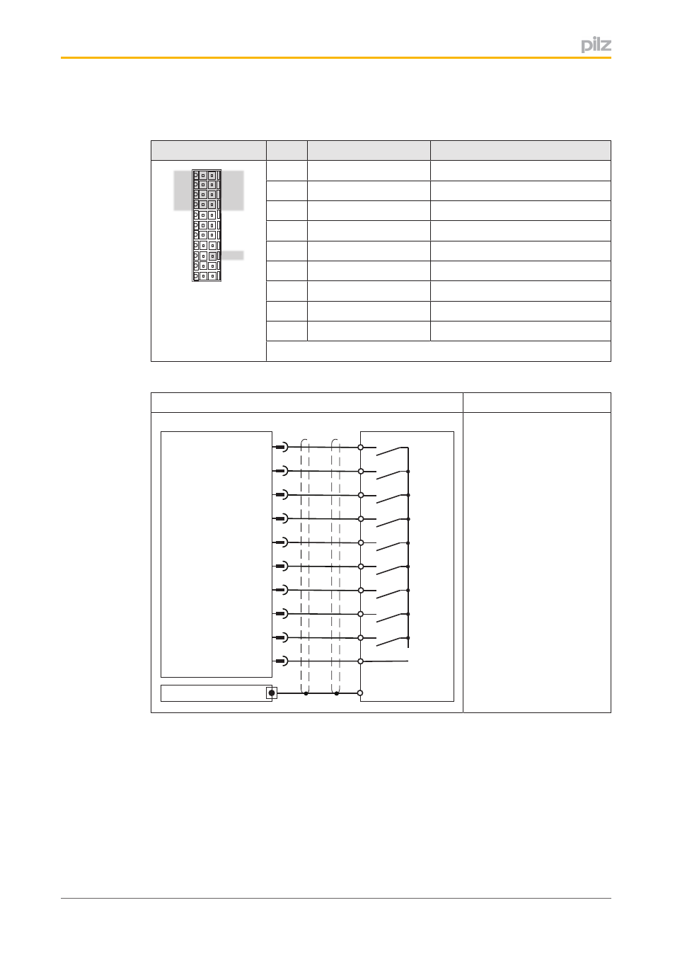
6.4
Digital inputs
Connector X30
Pin
Designation
Description
1
2
3
4
5
6
7
8
9
10
11
12
13
14
15
16
17
18
19
20
21
22
X30
1
SS1 Activate
Activate safety function SS1
2
I0
Activate safety function
3
I1
Activate safety function
4
I2
Activate safety function
12
I3
Activate safety function
13
I4
Activate safety function
14
I5
Activate safety function
15
I6
Activate safety function
20
Reset
Input for reset
Connector pin assignment
Input circuit
Digital input
1
I0
2
3
4
0V
12
24 V
I/O-GND
X30
I4
I3
I2
I1
I5
13
14
21
SS1 Activate
15
I6
20
Reset
Shield
Servo Amplifier
Shield
Shielded cable
Max. cable length: 30 m
24 VDC
Referenced to earth
Connection
6.5
Digital outputs
6.5.1
Supply voltage
The digital outputs need a 24 VDC supply.
}
When selecting the power supply, please refer to the requirements stated under “Tech
nical Details”.
}
The power supply must be able to bridge a power outage of 20 ms.
- PMCprimo DriveP.24/ABB/4/0/0/208-480VAC PMCprimo DriveP.06/AB0/2/0/0/208-480VAC PMCprimo DriveP.06/AB0/3/0/0/208-480VAC PMCprimo DriveP.24/AA0/5/0/0/208-480VAC PMCprotego D.06/000/0/0/2/208-480VAC PMCprotego D.24/000/0/0/2/208-480VAC PMCprotego D.06/010/0/0/2/208-480VAC PMCprotego D.06/100/0/0/2/208-480VAC PMCprotego D.06/200/0/0/2/208-480VAC PMCprotego D.24/200/0/0/2/208-480VAC PMCprotego D.24/100/0/0/2/208-480VAC PMCprotego D.24/010/0/0/2/208-480VAC PMCprotego S2-2 PMCprotego S2-2-C