2 output test, Output test – Pilz PMCprimo DriveP.06/AA0/4/0/0/208-480VAC User Manual
Page 17
Function description
Operating Manual PMCprotego S22(C)
1002529EN02
17
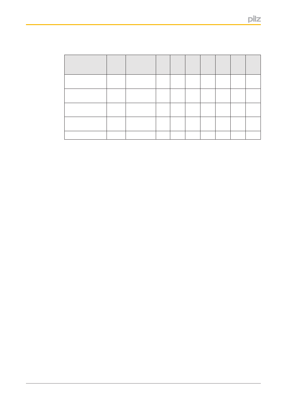
The table below shows which outputs signal the status of which safety function.
Output
In
ternal
error
No safety
function
activated
SS1
SS2
SOS
SLS
SSR
SDI
SLI
STO Acknow
ledge
x
x
x
x
x
x
x
x
x
SSA Safe Stand
still Acknowledge
x
x
x
SDA Safe Direc
tion Acknowledge
x
SRA Safe Range
Acknowledge
x
x
x
Ready
x
x
x
x
x
x
x
x
Signals at the output
}
“0” signal (0 V) at the output:
–
Output is high impedance
–
No current to the load
–
Safety function not activated
}
“1” signal (+24 V) at the output:
–
Output is low impedance
–
Current is supplied to the load
–
Safety function activated
Supply voltage
}
24 VDC connection to supply the safety card's digital outputs
4.2.2.2
Output test
The outputs are tested regularly:
}
Outputs that are switched on are checked via regular off tests.
–
Test pulses for outputs that are switched on: see technical details
–
Outputs that are switched on are switched off for the duration of the test pulse.
–
The load must not switch off because of the test.
}
Outputs that are switched off are checked via regular on tests.
–
Test pulses for outputs that are switched off: see technical details
–
Outputs that are switched off are switched on for the duration of the test pulse.
–
The load must not switch on because of the test.
Testing for shorts
}
A test is regularly carried out to check for shorts between the outputs.
- PMCprimo DriveP.24/ABB/4/0/0/208-480VAC PMCprimo DriveP.06/AB0/2/0/0/208-480VAC PMCprimo DriveP.06/AB0/3/0/0/208-480VAC PMCprimo DriveP.24/AA0/5/0/0/208-480VAC PMCprotego D.06/000/0/0/2/208-480VAC PMCprotego D.24/000/0/0/2/208-480VAC PMCprotego D.06/010/0/0/2/208-480VAC PMCprotego D.06/100/0/0/2/208-480VAC PMCprotego D.06/200/0/0/2/208-480VAC PMCprotego D.24/200/0/0/2/208-480VAC PMCprotego D.24/100/0/0/2/208-480VAC PMCprotego D.24/010/0/0/2/208-480VAC PMCprotego S2-2 PMCprotego S2-2-C