1 inputs, Inputs – Pilz PMCprimo DriveP.06/AA0/4/0/0/208-480VAC User Manual
Page 15
Function description
Operating Manual PMCprotego S22(C)
1002529EN02
15
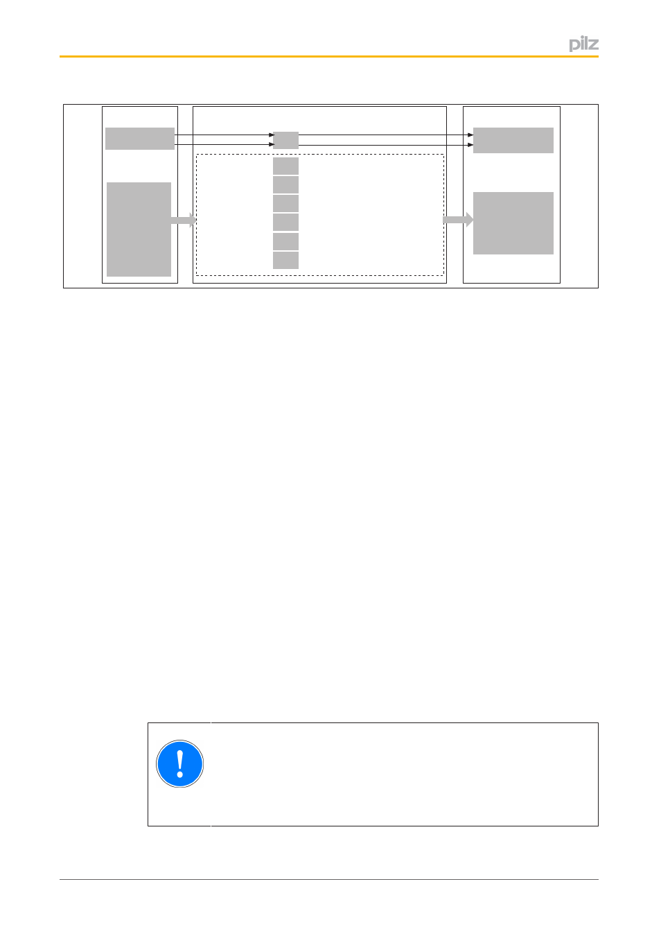
SOS
SSA Safe Standstill Acknowledge
SS1
SS2
SLS
SSR
SDI
SLI
SSA Safe Standstill Acknowledge
SRA Safe Range Acknowledge
SRA Safe Range Acknowledge
SDA Safe Direction Acknowledge
SRA Safe Range Acknowledge
SSA Safe Standstill Acknowledge
Safety Functions
SS2 Activate
SOS Activate
SLS Activate
SSR Activate
SDI Pos Activate
SDI Neg Activate
SLI Activate
O3
O2
O1
O0
STO Acknowledge
Ready
SS1 Activate
Reset
I0
I4
I5
I3
I2
I1
I6
Inputs
Outputs
Fig.: Inputs and outputs
4.2.1
Inputs
The safety card has safe singlepole inputs.
Inputs with fixed assignment:
}
SS1 Activate: Safe Stop 1
}
Reset: Additional safe input to reset the safety card after an error
The singlepole digital inputs I0 … I6 are used to activate the safety functions. Inputs are
assigned to the safety functions in the safety card's Configurator. The following signals are
available to activate the safety functions:
}
SS2 Activate: Safe Stop 2
}
SOS Activate: Safe Operating Stop
}
SSR Activate: Safe Speed Range
}
SLS Activate: Safely Limited Speed
}
SDI Neg Activate: Safe Direction, negative
}
SDI Pos Activate: Safe Direction, positive
}
SLI Activate: Safely Limited Increment
Signals at the input
}
1/0 pulse edge at the input: Safety function is activated
}
“0” signal (0 V) at the input:
–
Safety function is activated
}
“1” signal (+24 V) at the input:
–
Safety function is not activated
NOTICE
Inputs "SS1 Activate" and "Reset" must always be connected.
In the case of all inputs, only tested outputs from a safety control system
may be connected.
- PMCprimo DriveP.24/ABB/4/0/0/208-480VAC PMCprimo DriveP.06/AB0/2/0/0/208-480VAC PMCprimo DriveP.06/AB0/3/0/0/208-480VAC PMCprimo DriveP.24/AA0/5/0/0/208-480VAC PMCprotego D.06/000/0/0/2/208-480VAC PMCprotego D.24/000/0/0/2/208-480VAC PMCprotego D.06/010/0/0/2/208-480VAC PMCprotego D.06/100/0/0/2/208-480VAC PMCprotego D.06/200/0/0/2/208-480VAC PMCprotego D.24/200/0/0/2/208-480VAC PMCprotego D.24/100/0/0/2/208-480VAC PMCprotego D.24/010/0/0/2/208-480VAC PMCprotego S2-2 PMCprotego S2-2-C