Pilz PMCprimo DriveP.06/AA0/4/0/0/208-480VAC User Manual
Page 26
Function description
Operating Manual PMCprotego S22(C)
1002529EN02
26
}
"STO Acknowledge" output: “0” Signal
Safety function is activated
}
By a 1/0 pulse edge at the input "SS2 Activate".
}
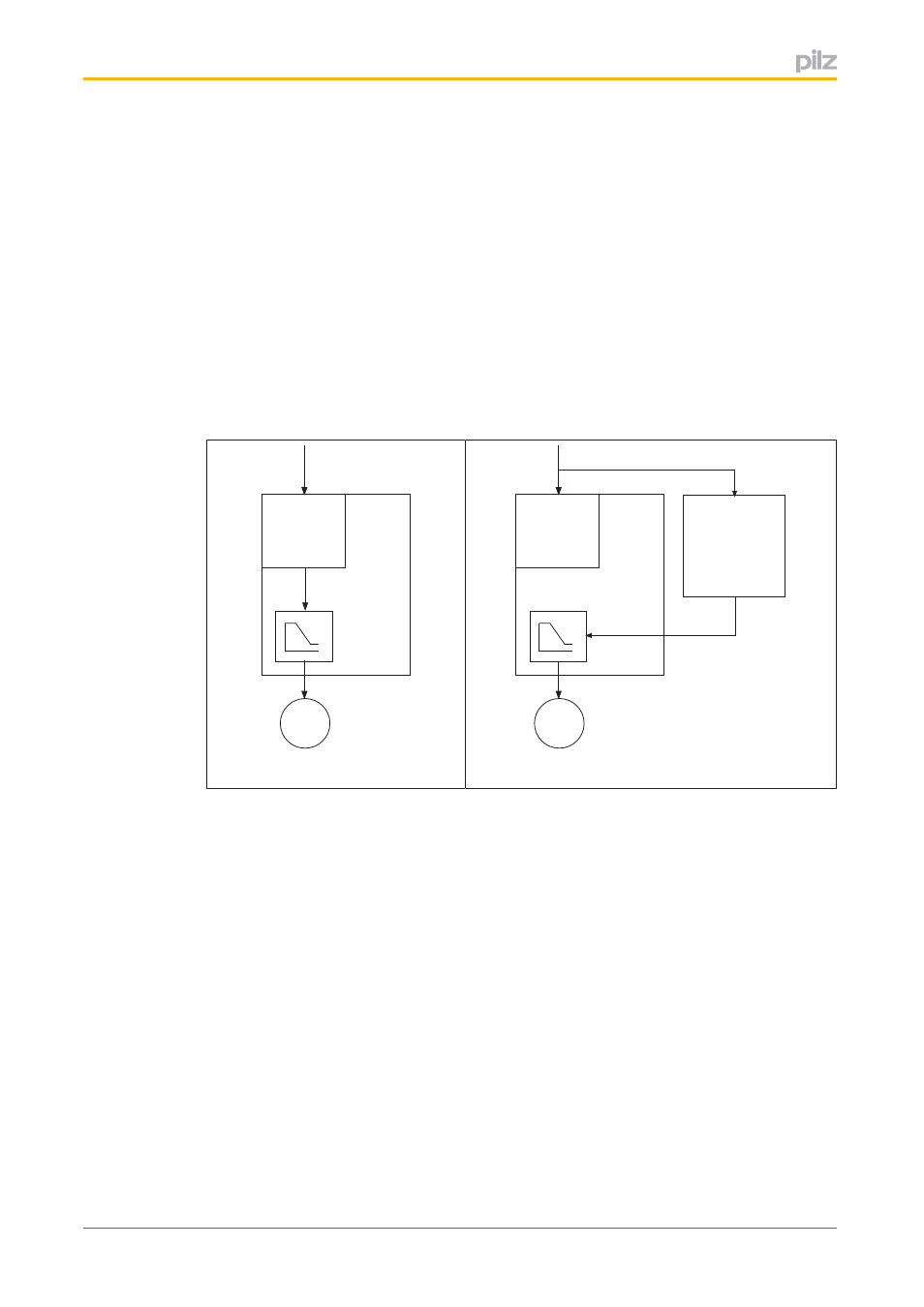
The method by which the servo amplifier receives the command for controlled braking
of the motor is defined in the Configurator:
–
Driveactivated: After the safety function is triggered, the safety card issues a com
mand to the servo amplifier for controlled braking of the motor. The braking ramp is
configured in the Configurator.
–
Controlleractivated: After the safety function is triggered, the control system is
sues a command to the servo amplifier for controlled braking of the motor. The
braking ramp must only be configured in the Configurator if monitoring of the brak
ing ramp is also activate there.
Safety Card
Servo Amplifier
M
Input
v
t
Driveactivated braking ramp
Safety Card
Servo Amplifier
Controller
M
Input
v
t
Controlleractivated braking ramp
Reaction:
}
Controlled braking of the drive, with the configured braking ramp.
}
The drive remains in a controlled standstill and is monitored for "safe standstill".
}
Output "SSA Safe Standstill Acknowledge": "1" signal
- PMCprimo DriveP.24/ABB/4/0/0/208-480VAC PMCprimo DriveP.06/AB0/2/0/0/208-480VAC PMCprimo DriveP.06/AB0/3/0/0/208-480VAC PMCprimo DriveP.24/AA0/5/0/0/208-480VAC PMCprotego D.06/000/0/0/2/208-480VAC PMCprotego D.24/000/0/0/2/208-480VAC PMCprotego D.06/010/0/0/2/208-480VAC PMCprotego D.06/100/0/0/2/208-480VAC PMCprotego D.06/200/0/0/2/208-480VAC PMCprotego D.24/200/0/0/2/208-480VAC PMCprotego D.24/100/0/0/2/208-480VAC PMCprotego D.24/010/0/0/2/208-480VAC PMCprotego S2-2 PMCprotego S2-2-C