5 reaction times, Reaction times – Pilz PMCprimo DriveP.06/AA0/4/0/0/208-480VAC User Manual
Page 45
Function description
Operating Manual PMCprotego S22(C)
1002529EN02
45
4.5
Reaction times
The reaction times refer exclusively to the inputs and outputs on a servo amplifier with
safety card when:
}
The signal at the inputs changes
}
The limit value is exceeded
}
Internal errors are present
To determine the overall reaction times, the corresponding internal processing times in the
servo amplifier, bus systems, periphery devices and controllers must also be taken into ac
count.
Processing time of the digital input
The response and error reaction time takes into account the following processing times:
}
Processing time of digital input T
IN
: The time it takes for a "0" or "1" signal in the safety
card to be detected once a signal has changed at the input. The processing time takes
into account the input filter time, temperature drift, spread of components, etc.
}
Internal processing times of the safety card
–
T
CYCLE
: Scan time of the safety card's processor system
–
T
OUT
: Processing time for the safety card's shutdown path
}
T
PULSE
: Processing time for the safe pulse disabler in the servo amplifier
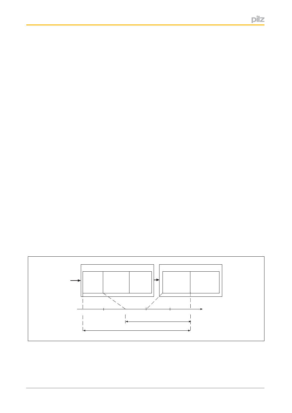
Response time:
}
The time it takes for the shutdown signal to be provided for the servo amplifier's power
element, once a signal has changed at the input
T
IN
+ T
CYCLE
+ T
OUT
+ T
PULSE
Error reaction time:
}
The time it takes for the shutdown signal to be provided for the servo amplifier's power
element, once a limit value has been exceeded or an internal error has occurred.
T
CYCLE
+ T
OUT
+ T
PULSE
Input
T
IN
Controller
T
CYCLE
Output
T
OUT
PMCprotego Sx
PMCprotego Dx
Pulse disabler
T
PULSE
Power element
t (ms)
3
5
1
0
Error reaction time = 3 ms
Response time = 5 ms
2
4
- PMCprimo DriveP.24/ABB/4/0/0/208-480VAC PMCprimo DriveP.06/AB0/2/0/0/208-480VAC PMCprimo DriveP.06/AB0/3/0/0/208-480VAC PMCprimo DriveP.24/AA0/5/0/0/208-480VAC PMCprotego D.06/000/0/0/2/208-480VAC PMCprotego D.24/000/0/0/2/208-480VAC PMCprotego D.06/010/0/0/2/208-480VAC PMCprotego D.06/100/0/0/2/208-480VAC PMCprotego D.06/200/0/0/2/208-480VAC PMCprotego D.24/200/0/0/2/208-480VAC PMCprotego D.24/100/0/0/2/208-480VAC PMCprotego D.24/010/0/0/2/208-480VAC PMCprotego S2-2 PMCprotego S2-2-C