4hitec 2.4ghz system set-up, Optima series receiver features – HITEC Eclipse 7 Pro User Manual
Page 6
4
Hitec 2.4GHz System Set-up
Optima Series Receiver Features
As of this writing, there are three Optima 2.4GHz receivers that are compatible with the Eclipse 7 Pro .The Optima 6, Optima 7
and the Optima 9 channel products are loaded with a variety of functions that are sure to deliver a satisfying R/C experience.
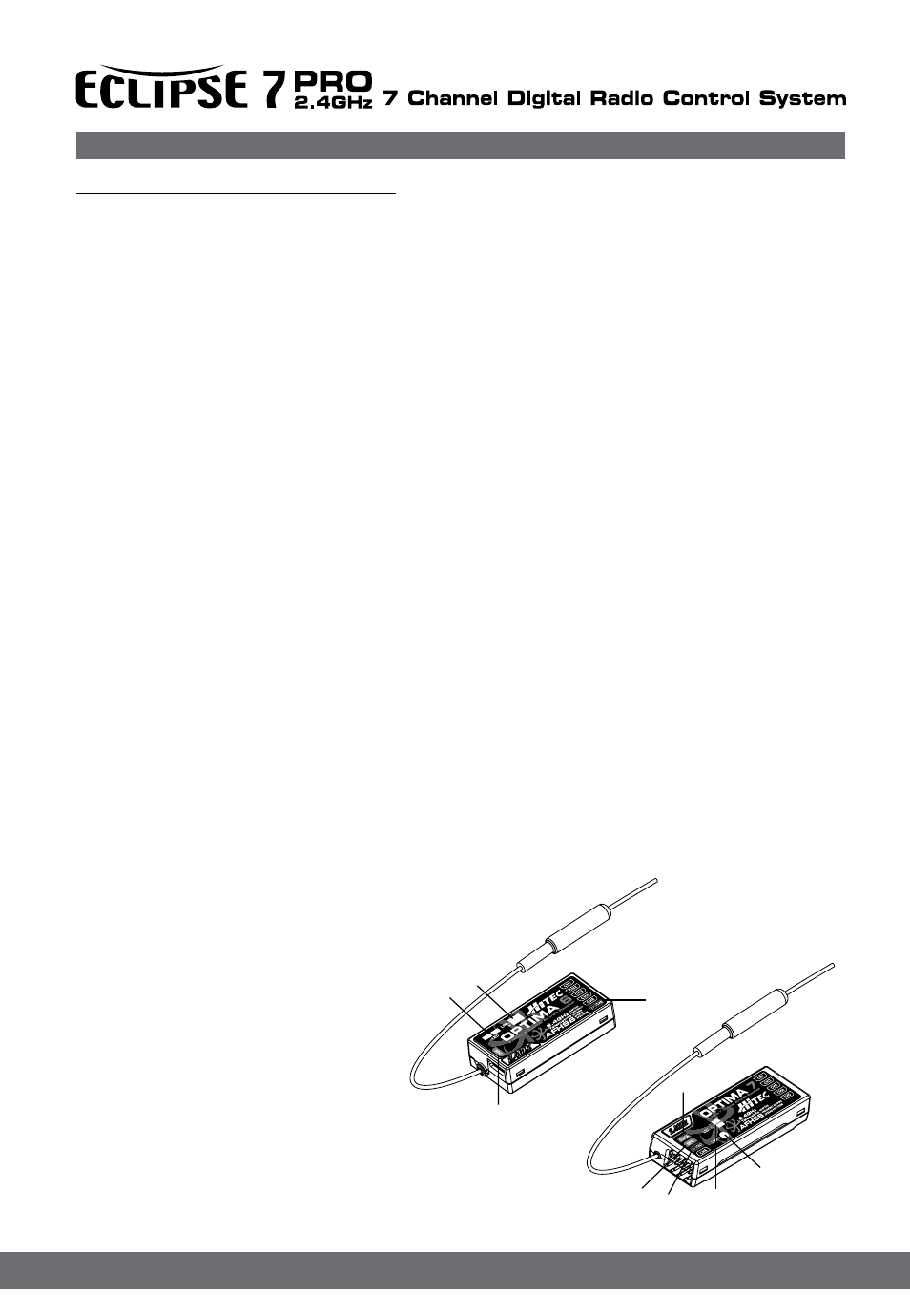
1. Telemetry Sensor and System Port
A three pin servo plug connector port is featured on the Optima 7 and 9 ch receivers. Using the HPP-22 PC interface acces
sory this port serves to facilitate upgrading the devices software and interfacing the optional onboard sensor station.
2. Function Button
Used for Linking(ID-Setting) the receiver to a Eclipse 7 Pro , entering Fail-Safe / Hold mode setup function.
3. Dual LED Status Indicator
Indicates the set-up process codes and use status
4. SPC Supplementary Power Connection
Power the Optima receiver function with up to a 35V. motor battery. Details about the SPC system can be found on page 9.
5. Channel Output and Battery Input Ports
The ports for battery power, servos, gyros and other accessories are located at each end of the streamlined Optima receivers.
6. Jumpers
The jumper is installed at the factory and is used when the receiver is powered by an electronic speed control, a commercially
available B.E.C. (battery eliminator circuit), dedicated 4.8 to 6V. NiMH battery pack, or *2S Li-Po/Io/Fe batteries. The jumper is
removed when the receiver is powered using the SPC feature as described in more detail on page 9.
(*Verify your servos are rated for use with these higher voltage batteries or use a regulator.)
Normal / Scan Mode Selectable
Select between two operational signal types. See page 6 for details.
FAIL-SAFE Option
Servos and other accessories may be programmed with a FAIL-SAFE point in the event power to the receiver is interrupted.
See page 7 for details..
Onboard Receiver Battery Warnings
Know when your on-board battery is low with direct telemetry feedback to your transmitter. See page 8 for details.
1. Function Button
2. Dual LED Status Indicator
3. Channel Output and Battery Input Ports
4. SPC (Supplementary Power Connection)
5. Telemetry Sensor and System Port
1
1
3
3
4
4
5
2
2