HITEC Eclipse 7 Pro User Manual
Page 58
56
The following example shows how the Eclipse 7 Pro may be programmed for a helicopter model. Your model’s settings will be
dependent on the setup and linkages. If you’re not sure about the settings for your particular model, please ask an experienced
pilot for assistance.
Eclipse 7 Pro Helicopter (HELI) Programming
This section describes how to use the Eclipse 7 Pro helicopter functions (model type HELI). Descriptions of the other functions,
such as endpoints, dual rates, expo, etc., are contained in the aircraft (ACRO) section. The HELI menu provides three flight
conditions in addition to the normal one (NOR). ST1 may be used for forward flight and mild aerobatics, ST2 may be used for
inverted, and ST3 is used for autorotation.
Helicopter Functions Map
Helicopter Setup Example
R->T Rudder->Throttle mixing
GYRO Gyro Settings
HOLD Throttle Hold
THCV Throttle Curve
PTCV Pitch Curve
RVMX Revolution mixing
SWAH Swashplate settings (120’, 140’ 180’)
MX.SS Mix Switch Select
Hovering Pitch Adjusting knob
Hovering Throttle Adjusting knob
Helicopter Trimming Chart
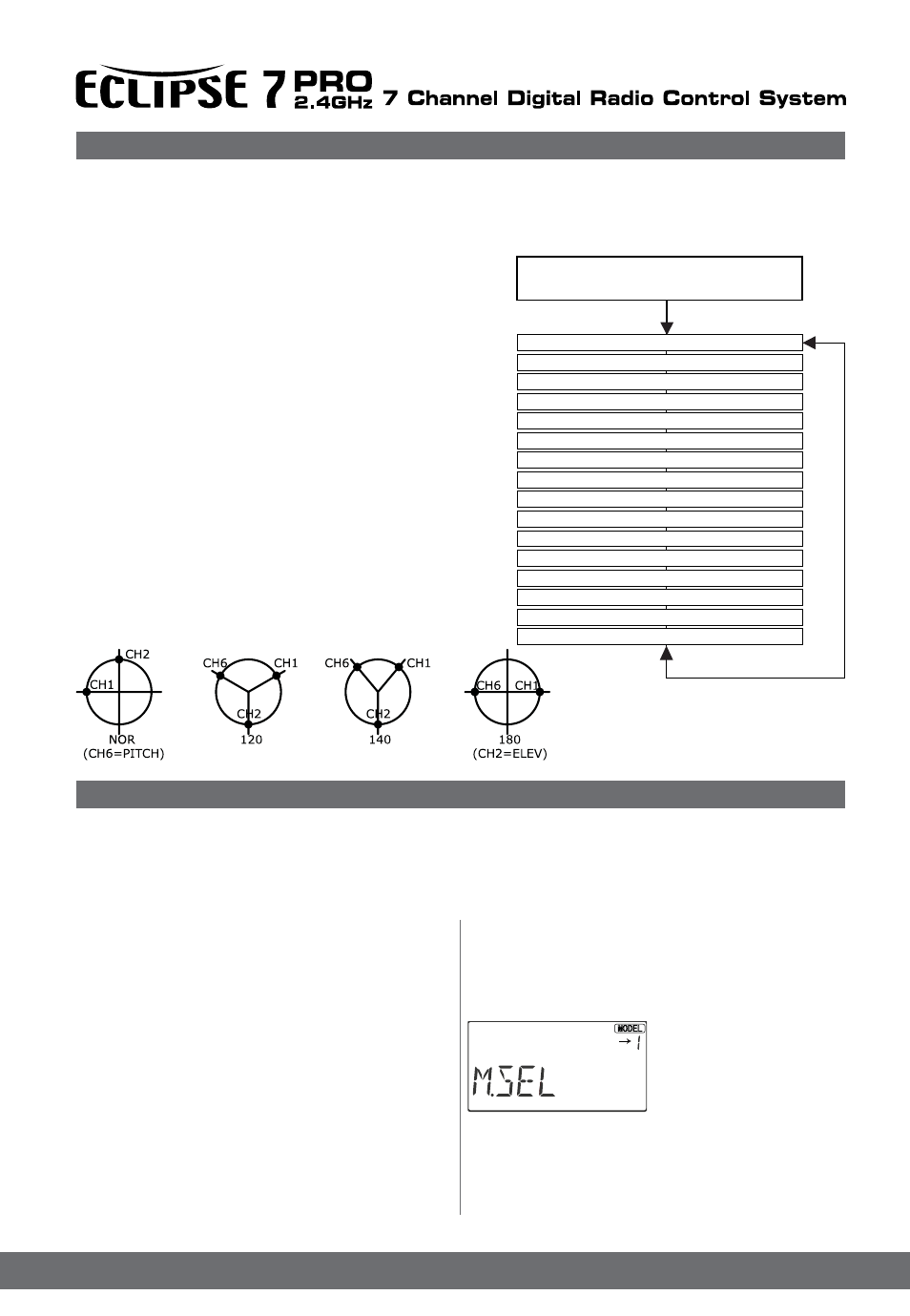
The Eclipse 7Pro system comes with three choices for the helicopter’s
swashplate arrangement, which may be found in the setup menu:
normal (NOR), 120 (120’), 140(140’)and 180 (180’). NOR is the standard
swashplate where one servo each performs the collective pitch, elevator,
and aileron functions. 120 ,140 and 180 are intended for three-servo
swashplates needing special mixing to get the servos to properly provide
the required pitch, elevator, and aileron functions.
Eclipse 7 Pro Helicopter (HELI) Programming
Helicopter Setup Instructions
The helicopter setup procedure presented below uses a
standard helicopter setup, one servo each for ailerons
and elevator. You can use a similar procedure to set up
your own model; your setting’s numbers and percentages
will probably be different.
1. In the helicopter, install each servo and hook up the
aileron, elevator, throttle, rudder, and pitch pushrods to
the servos in accordance with the model’s instructions
or plans. Be sure that all of your servos are plugged
into the proper receiver channels:
CH1 - Aileron CH5 - Gyro
CH2 - Elevator CH6 - Pitch
CH3 - Throttle CH7 - Aux. or heading hold control
CH4 - Rudder
If your model uses 120 , 140 or 180 swash programming,
plug in the servos as indicated in the table on page ??.
We recommend that you do this programming exercise
with the servos installed in the model and connected to
the respective control surfaces. This will enable you to
immediately see the effect of each programming step.
2. Model Memory. Turn
on your transmitter while
holding the two Edit Display
keys. This gets you
into the model select (M.
SEL) menu. Press the Cursor
Right button to move to
a new model memory. The model number of the model
memory you selected will be flashing
. The figure shows Memory #1.
3. Model Type. Press the Down arrow five times. The word
ACRO will appear, flashing on and off. Press the Left or
120˚ 140˚ 180˚ only
Press both
Edit/Display key
End Point Adjust [ EPA ]
Dual Rates [ D/R ]
Exponential Settings [ EXP ]
Flight Condition Select [ FLT.C ]
Subtrim [ S.TRM ]
Servo Reverse [ REV ]
Throttle Cut [ T.CUT ]
Programmable Mixer #1 - #2 [ PMX- ]
Rudder->Throttle mix [ R->T ]
Gyro Settings [ GYRO ]
Throttle Hold [ HOLD ]
Throttle Curve [ THCV ]
Pitch Curve [ PTCV ]
Revolution mixing [ RVMX ]
Swashplate settings (120’, 140’ 180’) [ SWAH ]
Mix Switch Select [ MX.SS ]
Voltage/ Timer Display
Normal Display Mode
Flashing