46 competition glider quick setup instructions – HITEC Eclipse 7 Pro User Manual
Page 48
46
Competition Glider Quick Setup Instructions
the F A offset (see previous step).
22. Center the camber knob, also known as the VR1
knob, on the left back of the transmitter. Be sure to center
all of the trims, and get all of the servo arms to be near
neutral. Use the clevises to get as close as you can.
This way you won’t run out of subtrim authority. You can
make fine adjustments to the positions of the two outer
ailerons using the aileron trim (AIL.T) function in the
programming menu. Now,
you can set the neutral
position of the two inboard
flaps (CH6 and CH7)
relative to each other
using the dual flap trim (DFL.T) knob (VR2). Then use
the subtrims (STRM) to set all the remaining controls the
desired neutral locations.
and down travel for each flap, which is handy for models
which have hinging that prevents motion in one direction
We suggest that you set the mixing rate to 50% on all
four settings. You can increase this later if you find you
need more maneuverability.
17. Now all the servos should function properly for different
stick motions. When you move the right-hand stick
to the right, the servos on the right wing should move
the controls upwards, and the servos on the left should
move the left wing controls downward. Rudder and
elevator should also respond properly.
Spend some time getting the correct motions in this step.
If you try to do it later within the different mixing functions,
you will get all messed up!
18. Now we’ll input values for aileron differential. Press
one of the Up Down Edit buttons to get to ADIF. The
function is already activated, but it’s set to 100% on both
sides, zero differential.
19. The display shows highlighted MAS sign and numeral 1
flashing together . This means that we are programming the
aileron stick input into the right aileron servo, CH1.
. Normally,
we want to have more up
aileron travel than down
travel. Hold the aileron
stick to the right but leave the
percentage setting at
100%. Now move the aileron stick to the left and use the
Data -Decrease key to drop it to 60-70%.
20. Now we’ll repeat the
previous step for the left
aileron. Press the Cursor
Right key once, so that
the SLV and numeral 5 will be
flashing. Now we’ll set the
differential on the second aileron. Holding the aileron stick to
the left, we leave the percentage setting at 100%. Now move
the aileron stick to the right and use the Data -Decrease key
to drop it to 70% or so. Now, when you move the aileron stick,
each aileron will go up more than down.
21. Move to the full-wing camber control (F->A) menu,
and activate by pressing the Active/Inhibit (Clear) key.
For this function, we recommend using a setting of 100%
so the motion of all four wing servos is the same. It is
important to have flap and aileron horns that are the
same length, but if they differ (hopefully in pairs) it is
possible to make some corrections here. The camber chang-
ing
is done by turning the knob on the left back of
the transmitter (VR1 flap knob, on the left back of the
transmitter). The default settings for Flap Aileron
mixing are such that you get equal motion above and
below the neutral camber position. There is a neutral
point setting command in this menu, which can be
reached by pressing the Cursor Right key inside of the
F->A menu. However, we recommend not using this
command. It does move the flap neutral position relative
to the aileron neutral. Note that the motion dictated by
the Camber knob (VR1 knob) goes into both positive and
negative camber from the neutral point, unless you set
you can set the neutrals for the ailerons and flaps by using the
wing beds (if they’re foam wings) or matching up with the rest
of the wing. Don’t use the fuselage airfoil as these are often
far from parallel from one side to the other. Set the elevator
incidence per the manufacturer or plans, and the rudder should
be centered.
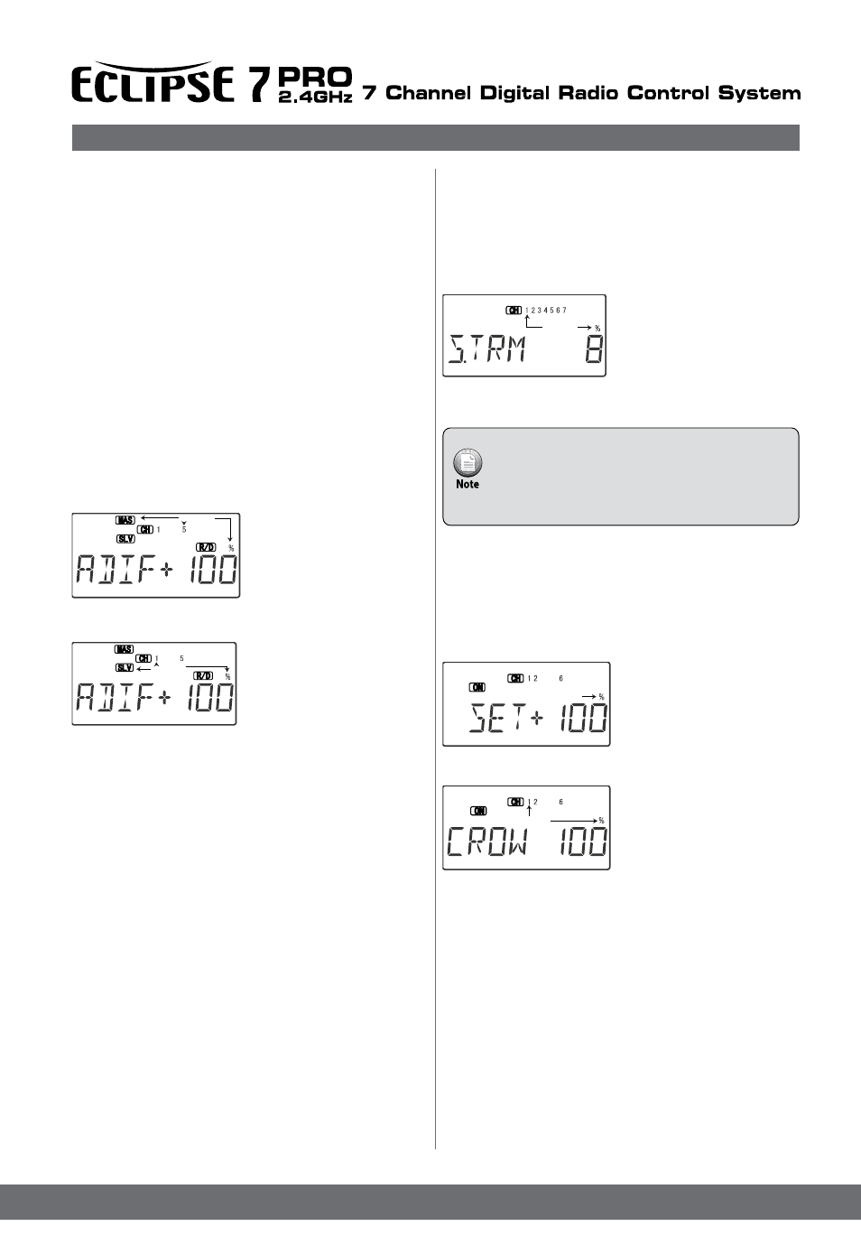
23. Set up the crow (also referred to as “butterfly”)
function for precise spot landings. The ailerons reflex
(go up), and the flaps drop with movement of the throttle
stick. Turn on by locating the CROW menu with the Up
Down Edit keys, then pressing the Active/Inhibit (Clear)
key. The On or Off display will be flashing, depending
on the Gear switch.
24. First set the CROW function
activation point.
Hit the Cursor Left key one time
to get to the offset setting menu.
Now move the throttle stick all
the way up. Enter that position
by pressing the Clear Active/
Inhibit key.
25. Next, set up the
throws for the ailerons. Hit
the Cursor Right key two
times to get to the aileron
setting menu (the Numeral 1
and percentage sign will be
flashing).
Use the Data +Increase or -Decrease keys to input
some percentage of aileron motion. Move the throttle
stick downwards and be sure the ailerons go UP with
crow. If they don’t, change the sign in front of the setting
number. You’ll probably want a fair amount, but not all, of
aileron travel. Start with about 50%. Be sure not to use
full travel, so you’ll have roll authority while on approach
in full crow command. Notice that you set the throw for
both ailerons at the same time: this is the reason to have
identical control arm lengths and neutral positions.
Flashing
Flashing
Flashing
Flashing
Flashing