50 glider model function descriptions – HITEC Eclipse 7 Pro User Manual
Page 52
50
Glider Model Function Descriptions
2. First, you’ll set the elevator (CH2) function offset
amount. Make sure S.TM1 is ON by moving the Flt.
Mode switch fully back. Verify it’s on by looking at the
flashing On indicator. Hit the Cursor Right key one time,
and a small arrow will appear over the numeral 2.
3. Next, set up the elevator (CH2) motion. Press the Data
+Increase or -Decrease keys to adjust the amount of
elevator offset. Use a small amount at first, as the
elevator is very effective.
4. Now set up the throws for the CH6 flap. Hit the Cursor
Right key one time, and the numeral 6 and percentage sign
will be flashing. Now use the Data +Increase or
-Decrease keys to adjust the amount of CH6 flap offset.
5. Next set up the throws for the CH7 flap. Hit the Cursor
Right key once, and the small arrow will move over the
numeral 7. Use the Data +Increase or -Decrease keys
to adjust the amount of CH7 flap offset.
6. Locate the S.TM2 menu by pressing the Up Edit key,
and then press the Active/Inhibit (Clear) key to turn it on.
Either the ‘Off’ or the ‘On’ display will be flashing,
depending on the position of the Flt. Mode switch.
7. Repeat the previous instructions for the second set of
inputs for elevator, CH6, and CH7.
AIL.T - Aileron trim
either two or four wing servos. It provides a simple way
to adjust the position of the outboard wing controls (CH1
and CH5) without resorting to the Speed Flap Trim menu.
When you adjust the Aileron Trim setting, you move the
two outboard wing controls together - they go upwards or
downwards together. In models with four wing servos,
you can use Aileron Trim together with the Dual Flap Trim
function (see below) to set any position of the wing
controls without using subtrims.
Using Aileron Trim
1. Turn on Dual Aileron
Trim by locating the AIL.T
menu with the Up Down
Edit keys.
2. Adjust the percentage to
neutralize them relative to each
other with the DATA keys
A->F - Aileron Flap mixing (4WNG only)
To roll a sailplane, we must increase the lift on one wing
and reduce lift on the other. The model will of course roll
towards the wing with reduced lift. For minimum drag
when turning, we want to have the way the lifting is done
vary smoothly along the span (i.e. zero at the root and
maximum at the tips). Unfortunately, to do this requires
a control surface that tapers from zero at the root to
maximum at the tip. Since this is impractical, we mix
from the ailerons to the flaps as shown below, so the
inner ailerons don’t move as far as the outer ones. This
is an approximation of the ideal lift for rolling, and will
reduce the drag created while banking the wings.
It’s more efficient to use both inboard and outboard wing
controls to make a turn. For a left turn, the left ailerons
go up, the right ones go down. The length of the arrows
is proportional to the control movement (notice that
to the sailplane trimming chart on page 51 for more
details.
6. Now press the Right key
to get to the flap setting
menu (the numeral 6 and per-
centage sign will be flashing
in the display). Press the
Data +Increase or -Decrease keys to set up the throws
for the flaps as desired. Move the throttle stick and be
sure the flaps go down with crow. If they don’t go down,
but go up instead, press the Clear Active/Inhibit key and
then press the other Data key to achieve the desired
down flap travel (this may depend on servo orientation).
You’ll probably want as much flap motion as possible -
90 is great if you can get it. Like the ailerons, you set
both flap offsets at the same time.
7. If you can’t get enough travel, go to the EPA menu and
be sure CH6 and CH7 are set as high as possible to get
90 flap travel. Of course, you can reduce them to get
the amount of travel that you’d like at full crow, but this is
better done in the Crow menu as given in the previous
step. It may be helpful to use long servo arms on the flap
servos to increase their effective throw.
Remember to try your crow setup out at higher altitudes
to verify that the trim doesn’t change rapidly. If you want
to steepen the descent, increase the flap downward
deflection while increasing the up aileron movement.
Caution: when setting up crow, do not call for too much
aileron “up” travel, or you’ll lose roll authority, and this
occurs at a crucial time, when your model is flying
relatively slowly on a landing approach. Always make
changes in small increments, don’t try to do it “all at once.”
S.TM1, 2 - Speed Flap Trim offsets (Camber mix) 1, 2 (4WNG
only)
Speed Flap Trim Offsets, together with flight conditions,
are a way to set up gliders with four wing servos(4WNG).
They do not appear in the two wing servo (2WNG) menu.
Speed Flap Trim offsets are used to offset the positions of
the elevator servo (CH2) and the inboard flaps (CH6 and
CH7) by flipping the Flt. Mode switch.
Together with the Flight Condition menus (FLT.C), you
can command any position of the inboard flaps, ailerons,
and elevator by flipping the Flt. Mode switch, and without
using Speed Flap Trims. Speed Flap Trim offset #1 is On
when the Flt. Mode switch is fully back, and is commonly
used for the “speed” mode, where the trailing edge is
reflexed. Speed Flap Trim offset #2 is On when the Flt.
Mode switch is fully forwards, and is commonly used for
setting up offsets needed for good launches.
Setting Up Speed Flap Trim Offsets
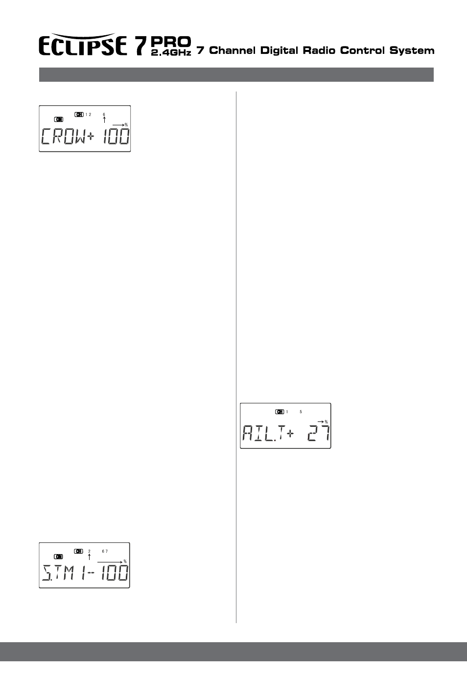
1. Start by locating the
S.TM1 menu with the Up
Down Edit keys, then
pressing the Active/Inhibit
(Clear) key. Either the ‘Off’
or the ‘On’ display will be flash-
ing, depending on the
position of the Flt. Mode switch. Also, the indicators for
CH2, CH6, and CH7 will appear at the top of the display.
Flashing
Flashing
Flashing