HITEC Eclipse 7 Pro User Manual
Page 29
27
Simple Transmitter Setup – Aerobatic Airplane (ACRO)
34. Servo EPA (End Point Adjustment). Now we’ll go
through and set the servo travels for each channel.
This is both helpful and important, because you can set
the throw of each servo, in each direction, so that there is
no binding. Binding is important because it causes very
high current drain, and can lead to a battery dying prematurely.
Another use for the EPA function is to adjust
the model’s total throws to match the recommended control
motions specified on the plans or instructions by
the model’s designer.
35. To set travels, get to the
EPA menu by pressing one
of the Up or Down Edit buttons
repeatedly until EPA
appears. In sequence, we’ll
set right aileron right travel, right aileron left travel, up and
down elevator travels, right and left rudder travels, open
and closed throttle positions, and left aileron travels.
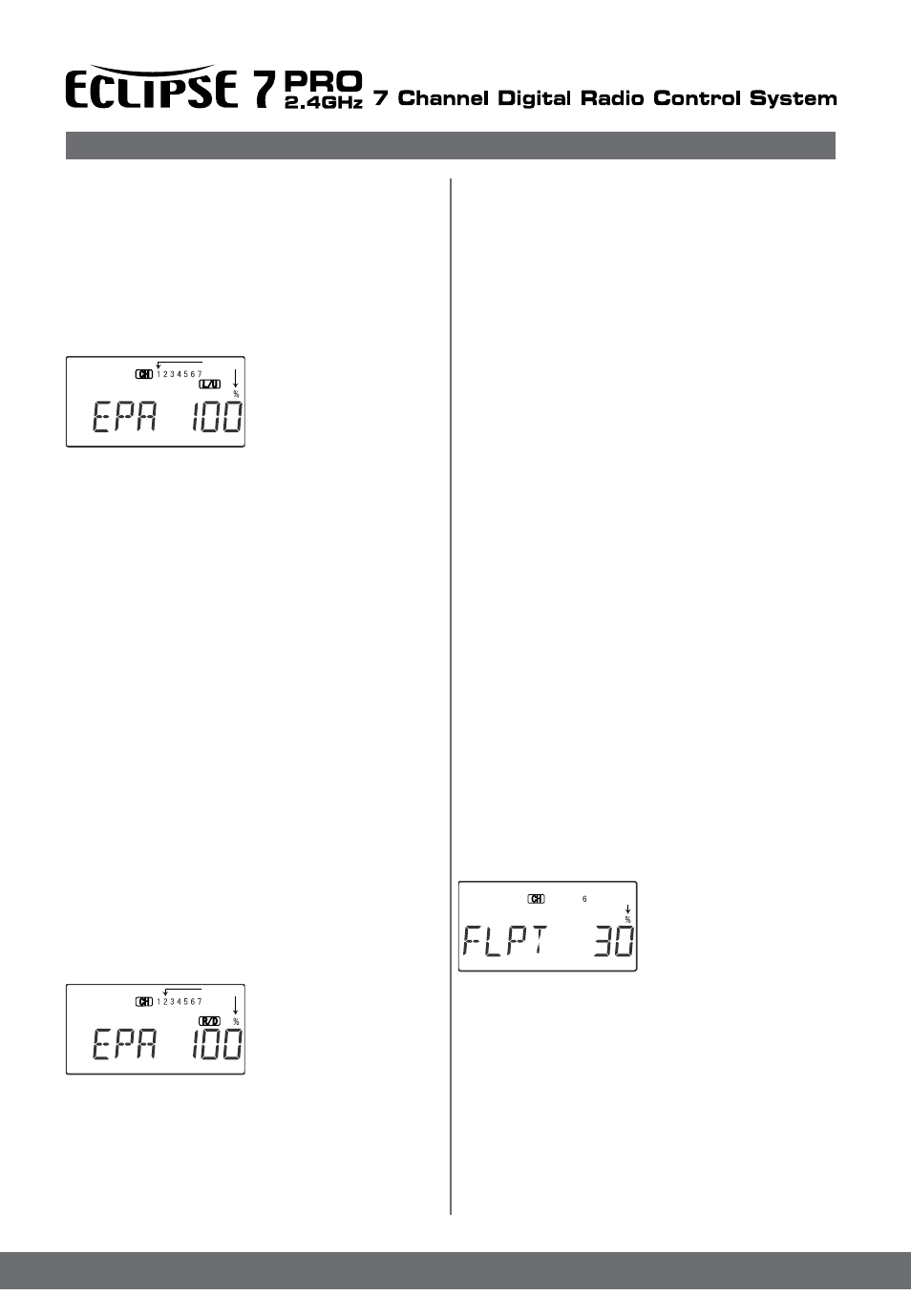
36. When you reach the EPA menu, you’ll see the screen
as shown. If you select The channel 1 (numeral 1 will be flash-
ing)
right aileron, the percent symbol will be flashing, and
you’ll notice that you can change the L/U indicator to R/D
(or vice versa) by moving the aileron (right) stick. You are
about to see that this is how you set the travel directions
independently for each stick motion.
37. To set the RIGHT aileron motion, move the aileron
stick all the way to the right and hold it. The letters “R/D”
should appear next to the flashing percent sign, meaning
you are setting either Right or Down travel (with ailerons
it’s right or left only, but the display is set up to use the
same indicators for elevator and throttle, thus the dual
meanings for the letters). Now if your servo is stalled or
binding, you’ll hear a buzzing sound. Hit the minus
-Decrease Data key until the buzzing stops. If the servo
is not buzzing, leave the setting at 100%. If you can,
choose a location for the pushrod on the servo arm so
that the throw is adjusted in the 90-100% range.
38. To set the right aileron’s LEFT motion, move the
aileron stick all the way to the left and hold it. The letters
“L/U” should appear next to the flashing percent sign
. Again listen and hit the
-Decrease Data key until the buzzing stops. If the servo
is not buzzing, leave the setting at 100%. (Remember,
you’re only setting the right aileron travel. You set the
other aileron’s travel in channel 6’s EPA.)
39. To set the UP elevator
motion, press on the Right
Cursor key until the
channel 2 will flashing.
Now move the right stick all
the way to the transmitter bot-
tom and hold it.
The letters “L/U” should appear next to the flashing
percent sign. Again listen for a buzzing sound to indicate
the servo is stalling, and hit the -Decrease Data key until
the buzzing stops.
If the servo is not buzzing, leave the setting at 100%.
40. Repeat the previous step for DOWN elevator by
moving the stick all the way to the top of the transmitter,
full “down” elevator. Check for binding and adjust the
percentage as before.
41. To set the throttle position at IDLE, first return to the
regular display and set the throttle trim to -25%. Then
go back to the EPA menu and press the Right Cursor
key until the channel number 3 will be flashing. Now
move the throttle stick all the way to the transmitter bottom
and hold it. The letters “L/U” should appear next to
the flashing percent sign. Listen for a buzzing sound to
indicate servo stalling, and hit the -Decrease Data key
until the buzzing stops. Change the setting to nearly but
not completely - close the throttle (engine idle).
Later you may increase or decrease this number so you
can’t accidentally shut off the engine using the trim tab.
42. To set the FULL throttle position, move the throttle
stick all the way to the transmitter top and hold it. The
letters “R/D” should appear next to the flashing percent
sign. [Notice that the Eclipse 7 Pro transmitter thinks of throttle
stick positions to the reverse of the way it seems, in
that with the throttle stick fully forwards - “up” towards the
transmitter top, is the Down position.] Listen for a buzzing
sound to indicate the servo is stalling, and hit the
-Decrease Data key until the buzzing stops. If the servo
is not buzzing, leave the setting at 100% or change your
linkage as necessary to fully open the throttle.
43. To set the RIGHT rudder motion, press the Right
Cursor key until the channel 4 will be flashing.
Now move the left stick all the way to the transmitter
right and hold it. The letters “R/D” should appear next
to the flashing percent sign. Listen for a buzzing sound
to indicate the rudder servo is stalling, and hit the Data
-Decrease key until the buzzing stops. If the servo is not
buzzing, leave the setting at 100%. You may wish to
increase or decrease this number depending on how
strongly the model reacts when the rudder is deflected.
Now move the stick to the left side, and repeat the setting
procedure for left rudder.
44. In the same manner as described above, be sure to
set EPA values for channels 5 (landing gear) and 6
(second aileron), if you have either.
45. If you wish to have the
flaps operate with the CH6
knob, go back to the FLPT
menu and input a number
greater than zero. Adjust
the number to get the
desired amount of flap travel as you turn the knob.
46. If you wish to have differential aileron travel, this can
be done in the flaperon menu. First, we’ll reduce the
down travel on the right aileron. Press the Right Cursor
key until the channel numeral 1 and MAS will flashing
Hold the aileron stick to the left and press the
-Decrease Data key until the number is smaller. 50-75%
is a good starting point. Watch to be sure you’re setting
the down travel on the right aileron.
47. Next, we’ll reduce the down travel on the left aileron.
Press the Right Cursor key until the channel numeral 1 and
SLV will flashing
Flashing
Flashing
Flashing