51 glider model function descriptions – HITEC Eclipse 7 Pro User Manual
Page 53
51
Glider Model Function Descriptions
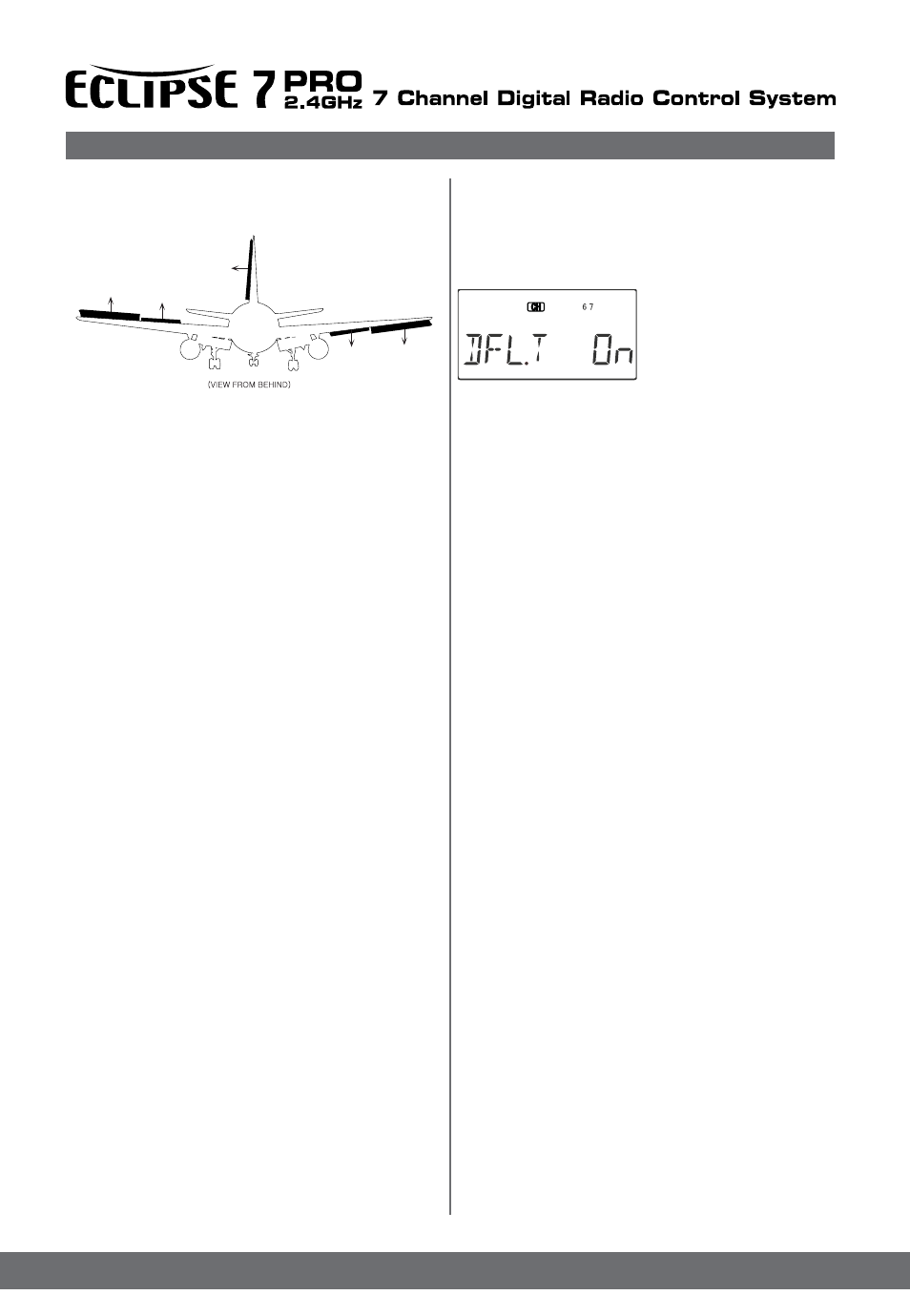
back of transmitter) to
move the two inboard flaps against each other - one goes
upwards, the other goes downwards. Together with the
Flap/Camber control knob (VR1), you can set any
position of the inboard flaps without using subtrims.
Using Dual Flap Trim
1. Turn on Dual Flap Trim
by locating the DFL.T menu
with the Up Down Edit
keys. The default is for it to
be on. If you wish to
disable the dual flap trim, press
the Active/Inhibit (Clear)
key so that the ‘inh’ display is shown.
2. Turn the VR2 knob one way or the other and observe
the response of both inboard flap servos. Adjust the knob
to neutralize them relative to each other. If you inhibit this
function, they’ll return to their original positions
Sailplane Trimming and Adjusting
The following chart gives procedures that may be
followed when trimming a new sailplane. The flights
should be made in near-calm conditions, and repeat them
several times before making adjustments. If any changes
are made, go back over the previous steps and verify, or
further adjust as necessary. One of the most critical
steps is the center-of-gravity (CG)/decalage testing (Step
3). Decalage is a fancy term describing the relative angle
difference between the wing and horizontal tail. Although
the control neutrals have been set in Step 1, there are
differing combinations of elevator trim and CG that
produce stable flight. In general, by moving the CG back
you get better performance and you reduce the stability,
making the model more difficult to fly and requiring more
attention from the pilot. Moving the CG back lessens the
download on the model’s tail, which means the wing and
tail are working more together and less against each
other as they do with a forward CG. Many contest flyers
use a CG position located between 35 and 40% of the
mean wing chord, which is near the back limits for
stability (the mean chord is just about the same as the
average chord, which is calculated by dividing the area
by the wing span). How you set your model up really
depends on your preferences. A nose-heavy model will
be easier to fly but will lack the performance of the back-
CG model. You should also set differential and/or rudder
coupling carefully. Incorrect settings will result in
needless increased drag, and may be checked fairly
easily. If you practice keeping the fuselage straight while
gently rocking the wings back and forth, you’ll learn how
to coordinate turns and won’t need coupled rudder any
more. You can also learn about the proper amount of
differential or rudder coupling by studying the figures of
the model circling in the “coordinating turns” section,
Chapter 5. Too much differential can make the model
sluggish when entering or exiting turns and banks.
Setting up butterfly can be tricky. The reader is referred
to the section earlier in this chapter which describes the
instructions contained in the chart’s line 4, 5, and 6.
Whatever you do, be sure to spend a lot of time trimming
Aileron->Flap mixing is turned on and off with the Flt.
condition switch. You can adjust the amounts of up and
down mixing independently, which is nice if your model’s
flaps are hinged on the bottom and they cannot move up
past a certain point.
Using Aileron->Flap Mixing
1. Turn on Aileron->Flap mixing by locating the A->F
menu with the Up Down Edit keys. The default is for it
to be inhibited (Inh). Press the Active/Inhibit (Clear)
key so that to activate of Flap Mixing.
2. First, you’ll set the aileron (CH1)->CH6 function mixing
amount. Make sure A->F is On by moving the Flt.
condition switch fully back. Verify it’s on by looking at the
flashing On indicator. Hit the Cursor Right key one time,
and SLV with the numeral 6 will be flashing .
3. To set the UP mix amount for the right flap, hold the
aileron stick to the right side (display shows R/D), and
press the Data Decrease key. Continue reducing the
percentage until the servo stops buzzing. If there’s no
buzzing, you can start with about 50%. If your model has
bottom-hinged flaps, you can get to 0% quickly by
pressing the Active/Inhibit (Clear) key.
4. Now set the Down mix amount for the right flap (CH6).
Holding the aileron stick to the left side (display shows
L/U), use the Data Decrease key to reduce the
percentage to about 50%.
5. Now we’ll do the same for the second flap servo (CH7).
Press the Cursor Right key once, to get to the left flap
(CH7) setting menu. A small arrow is displayed under the
numeral 7, showing that CH7 is the affected channel.
Move the aileron stick to the right (display shows R/D),
and press the Data Decrease key reducing the
percentage until you reach about 50%.
6. Set the up mix amount for the second flap (CH7) as
you did for the first flap servo. Hold the aileron stick to
the left side (display shows L/U) and press the Data
Decrease key to reduce the percentage to about 50%.
Again, if your model has bottom-hinged flaps, you can get
to 0% quickly by pressing the Active/Inhibit (Clear) key.
DFL.T - Dual Flap Trim (4WNG only)
Dual Flap Trim is a trimming function for gliders with four
wing servos, and does not appear in the two wing servo
(2WNG) menu. It provides a simple way to adjust the
position of the inboard flaps (CH6 and CH7) without
resorting to the subtrim menu. When you activate Dual
Flap Trim, you can turn the right-hand knob (VR2, located right
inboard ailerons are programmed to move a smaller
angle). Rudder coupling is also shown and may be
programmed with the R->A mixing function.