HITEC Eclipse 7 Pro User Manual
Page 37
35
Simple Transmitter Setup – Aerobatic Airplane (ACRO)
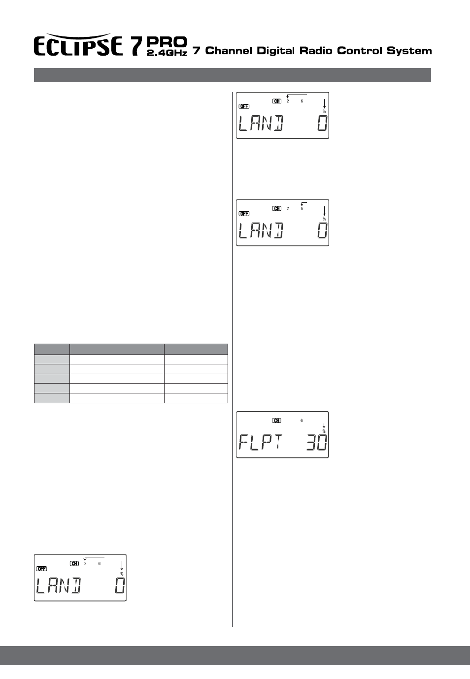
2. First the amount of elevator
offset is programmed.
The numeral 2 will be flashing
(representing elevator). You
may adjust the amount of travel
with the Data +Increase and
Decrease keys.
You may use anywhere between -100% and +100%, but a
small value of +10% or less is the recommended starting
value. Be careful as this has a very powerful effect on the
model’s trim. Press the
Active/Inhibit (Clear) key if you wish to reset to 0%.
3. To get to the flap travel
setting, press the Cursor
Right key. the channel numeral
6 will be flashing,
indicating the flap channel. You
may input any desired
flap travel with the Data +Increase and -Decrease keys.
The default is 0%, and you may set this anywhere from
-100 to +100% (check that there is no binding with large
flap deflections and aileron commands). With flaperons,
large motions should also be avoided because of
reduced aileron effectiveness. You may return to the 0%
settings by hitting the Active/Inhibit (Clear) key.
Note: At first, be very cautious using the LAND function
when you are flying slowly, as there could be a loss of roll
authority. Check out how it works at high altitude first.
FLPT - Flap Trim Function
The Flap Trim function is used to specify the amount of
flap travel produced by motion of the flap control (the
CH6 knob). With flaperons active, it may controls the motion
of both ailerons.
Setting Flap Trim function
1. Use the Edit Up Down arrow
keys to select the FLPT window.
2. Pressing the Data +Increase
or -Decrease key to input your
desired flap motion setting. The
30% default value produces
“reasonable” travel for many models, but you must try it out on
your own model to be sure. A 100% setting causes extreme
travel and is not recommended. You may want to set it to a
smaller number, say 10% for starters. If you wish to return to
the default 30% setting, press the Active/Inhibit (Clear) key.
You can toggle through the settings 0%, 30%, and 100%
by continuing to press this (Clear) key. Setting it to 0%
disables the flap knob, but the flaps will still respond to mixing
functions such as E->F and to the Landing function.
E->F - Elevator -> Flap Mixing
Elevator-to-flap mixing makes the flaps drop or rise when ever
you pull on the elevator stick. It is used to make tighter “pylon”
turns or squarer corners in maneuvers.
Elevator-to-flap mixing is set up so that the flaps droop (are
lowered) when up elevator is commanded.
Notice that this mixing function works with the flaperon setting.
If flaperon mixing (FLPN) AND E->F mixing are activated,
The motion of the master channel’s control is also
indicated by the R/D (= Right/Down) or L/U (= Left/Up)
indicator in the window.
6. Hold the master channel’s control to one side, and then
use the Data +Increase or -Decrease key to change the
percentage for the mixer. Verify that you get the proper
motion of the slave channel when you move the master.
If you don’t get a response to the master movement,
check that the mixer is turned on with its on -off switch
(either the Ch. 7 switch, or the Rudd D/R switch).
Change the percentage if the amount of travel is incorrect.
If you want to set the percentage to ZERO, press the
Active/Inhibit (Clear) key.
7. Move the master control to the other side of its travel
and then repeat the actions in the previous step to set the
amount of mixing on the other side. Use the Data
+Increase or -Decrease key to change the percentage
for the mixer until you get the response you want for the
second side.
[Knife-Edge Example : for a model that tucks under during
knife-edge flight, set up a mixer with Master = 4(Rudder),
and Slave = 2 (elevator). You want to get up elevator
mixed in for either direction of full rudder. Therefore, you’ll
set plus mixing on one side of the rudder stick, and
minus mixing on the other side. Normally only 5% to
10% mixing is needed to solve this problem.
MixerNo.
1
2
3
4
5
CH7SwitchForward
CH7SwitchForward
GearSwitchForward4
RudderSwitchForward
FltConditionSwitchForward
ACRO,GLID
ACRO,GLID
ACRO,GLID,HELI
ACRO,GLID,HELI
ACRO,GLID
MixerOnWhen...
Available menus
The LAND function simultaneously moves the flaps and
the elevator to defined positions to help make steep
descents or limit airspeed in dives. The controls move to
the defined positions by flipping the Flt. Mode switch fully
forward. If your model has a single flap servo on CH6,
the flap is dropped. If flaperons are active, you’ll want to
raise both to prevent tip-stalling with some up-elevator to
compensate, but you may want to experiment with small
values of down flaperons to slow the model down.
Use the elevator offset to maintain pitch trim when the
landing function is turned on.
Setting up Landing function
1. Use the Edit Up Down
arrow keys to select the
LAND window.
Depending on the position
of the landing switch, the
display will show OFF or ON.
The Flt. Mode switch turns on
LAND when all the way forward.
Flashing
Flashing
Flashing
Flashing
PMIX Switches
Land - Landing Function