HITEC Eclipse 7 Pro User Manual
Page 18
16
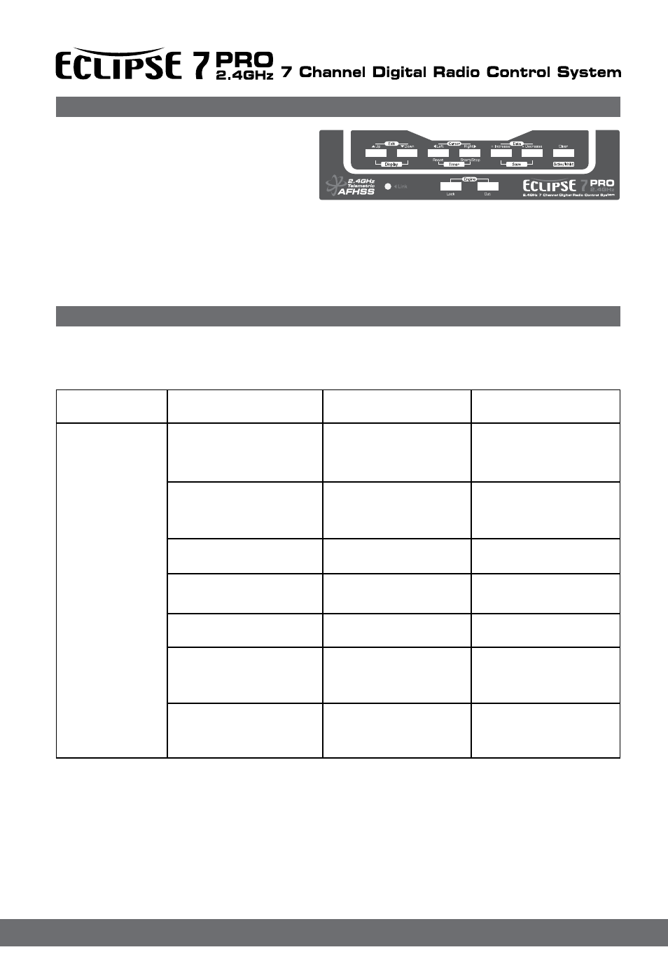
The buttons are used for different things as follows:
1.The Edit/Display Up & Down buttons (1)allow
you to move up and down within the model
menus, and move within the regular display.
select options within a particular function,
and control the timer function.
2.The Data +Increase & -Decrease buttons (3)allow you to increase or decrease the numerical settings for a function.
3.The Clear Active/Inhibit button (4)resets numbers, and turns functions on and off.
4.The Engine Lock button (5)holds the throttle channel while other channels may respond to the transmitter.
5.The Engine Cut button (6)closes the throttle so that you can kill the engine without touching the trim lever.
You'll learn how to use these buttons in the setup sections that follow
6.The link button Can be used for that link process between ECLIPSE 7 PRO to a Optima or Minima series receivers, entering
the power down mode for range checks, and the Normal/Scan Mode set-up
Transmitter Input Buttons
Receiver - Servo Connection List
The table below shows the hookups that should be used for each of the model types. Note that some functions shown will not
operate until they are activated in the transmitter.
The servo response varies with the selected function. Standard options are shown first.
Receiver channel
Aircraft (ACRO)
Glider (GLID)
Helicopter (HELI)
1
aileron or right aileron
or right flaperon (FLPN)
or right elevon (ELVN)
right aileron(or rudder for
rudder-elevator models)
roll
or swash servo 1 (120’)
or swash servo 1 (140’)
or swash servo 1 (180’)
2
Elevator or V-tail right side
(VTAL) or left elevon (ELVN)
or left Elevator(AILV)
elevator or V-tail right side
(VTAL)
Elevator
or swash servo 2 (120’)
or swash servo 2 (140’)
or swash servo 2 (180’)
3
throttle
spoiler, throttle (on-off
controlled by Gear switch)
throttle
4
rudder or V-tail left side
(VTAL)
rudder or V-tail left side
(VTAL)
yaw
5
landing gear
left aileron
gyro sensitivity
6
flap (controlled by VR1) or
left flaperon (FLPN) or left
aileron
right flap (4WNG) or single
flap
(2WNG)
pitch
or swash servo 3 (120’)
or swash servo 2 (140’)
or swash servo 2 (180’)
7
optional, controlled by VR2
or right Elevator(AILV)
left flap (4WNG) or propor-
tional
channel, controlled by VR2
(2WNG)
optional, controlled by Gear
switch