Light up the fan project 120, Project 117 higher pitch buzzer, Project 119 slow light & motion – Elenco Snap Circuits® Deluxe Sound & Light Combo User Manual
Page 69
-68-
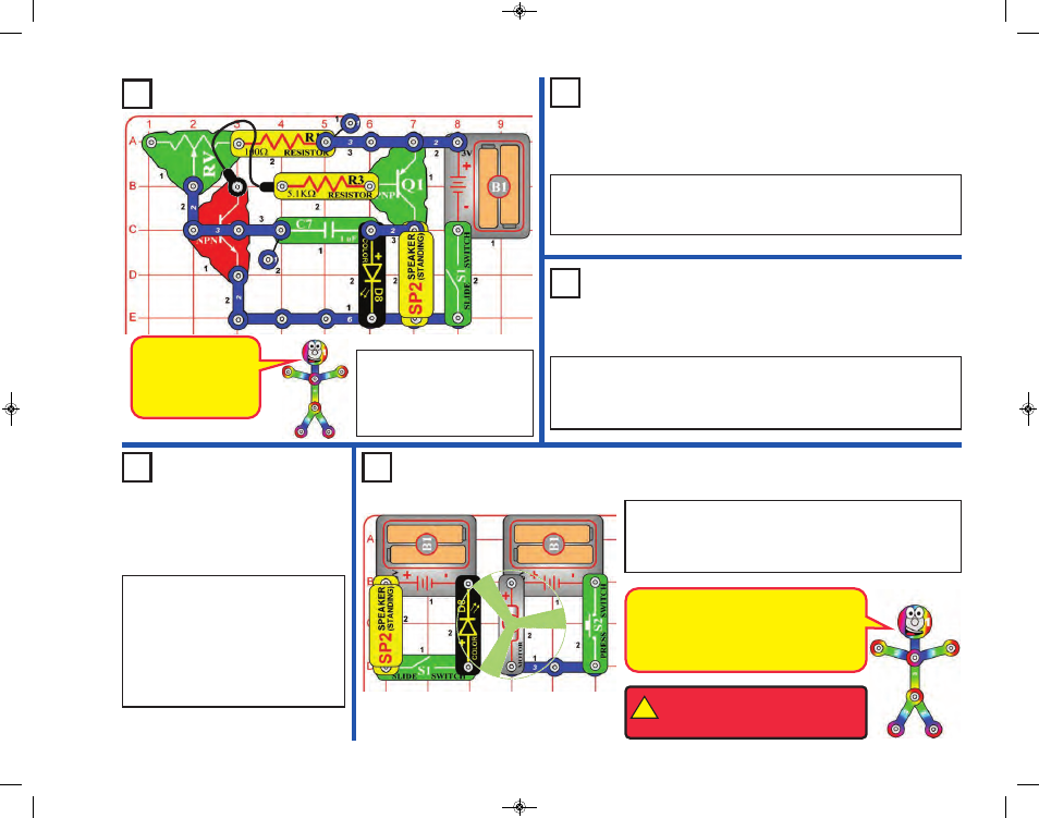
Project 116
Buzzer
Project 118
Photo Light & Motion
Project 119
Slow Light &
Motion
Light Up the Fan
Project 120
This circuit is an
oscillator, which uses
feedback to control
the pitch of the
sound.
!
WARNING:
Moving parts. Do not
touch the fan or motor during
operation.
The circuit with the color LED is not
electrically connected to the circuit with the
motor. This was done because the motor
produces electrical pulses as it spins, and
these pulses can confuse the color LED.
Project 117
Higher Pitch Buzzer
Build the circuit as shown and
turn on the switch (S1). Move
the lever on the adjustable
resistor (RV) to vary the pitch
of the buzzing sound.
Use the preceding circuit, but replace the 1mF capacitor (C7) with the
0.1mF capacitor (C2). The pitch of the tone is higher now, but the circuit
may not make noise on all settings for the adjustable resistor.
Use the circuits from projects 116-117, but add the photoresistor (RP)
across base grid locations B2-B4 (between RV and R1), on level 3. Vary
the amount of light on the photoresistor to change the sound, while also
varying RV.
Build the circuit as shown, place the glow fan on the motor
(M1), and turn on the slide switch (S1). Place the circuit in a
dark room and push the press switch (S2) to spin the fan.
The color LED (D8) lights up the spinning fan.
Use the circuits from projects 116-117,
but replace the 0.1mF capacitor (C2)
with the 100mF capacitor (C4), “+” to
the right. Turn the switch on and
patiently wait. The speaker will beep
and the color LED (D8) will flash every
5-20 seconds, depending on the
resistors.
SCC-350_Manual_Part_B.qxp 7/25/14 2:05 PM Page 13