Elenco Snap Circuits® Deluxe Sound & Light Combo User Manual
Page 126
-125-
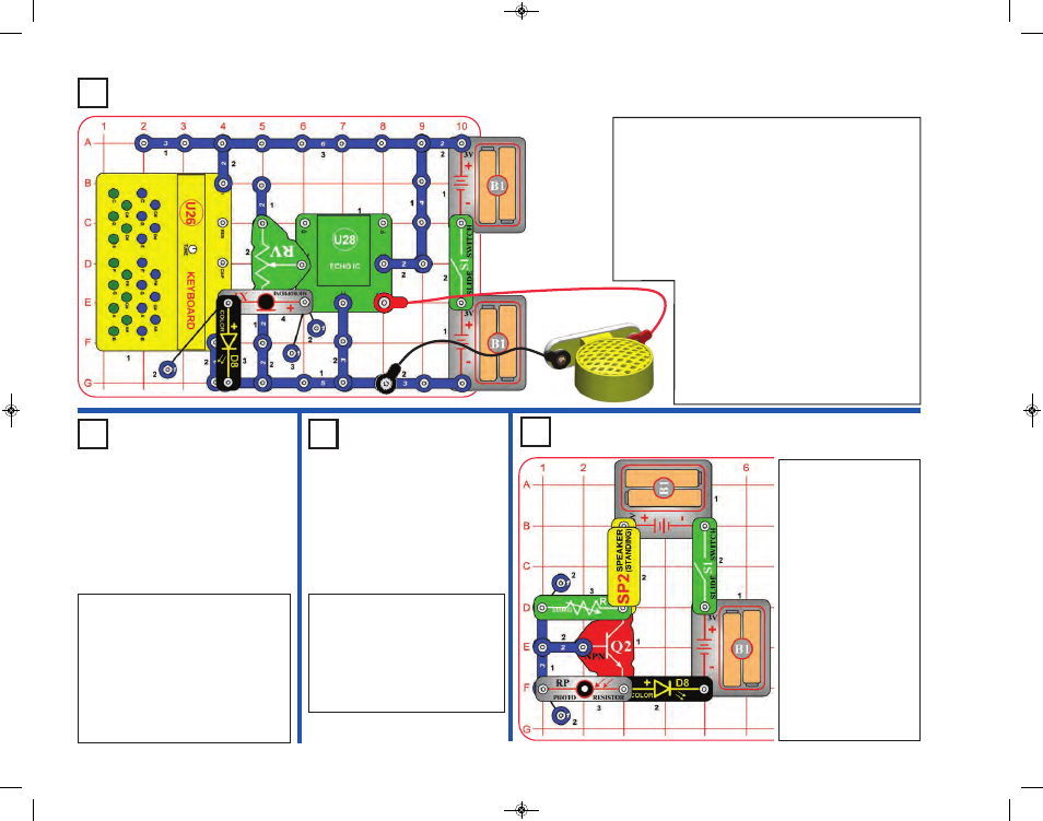
Build the circuit as shown. Place the circuit in a quiet
room. Connect the speaker (SP2) using the red & black
jumper wires, then hold it away from the microphone.
Turn on the slide switch (S1). Talk into the microphone
or press keys on the keyboard (U26), and listen the
echo on the speaker. Adjust the amount of echo using
the lever on the adjustable resistor (RV); move the
lever up for more echo or down for less echo. Try this
at different RV settings, because the effects are very
interesting with both high and low echo amounts.
The color LED (D8) lights when keys are
pressed but will be dim. It is easier to see
in a dimly lit room.
Note: You must hold the speaker away
from the microphone or the circuit may self-
oscillate due to feedback. You also need a
quiet room, with low background noise.
Project 268
LED Voice Keyboard Echo
Project 269
Photo LED
Keyboard
Echo
Project 270
Photo LED
Keyboard
Project 271
Audio Dark Light
Use the preceding circuit, but
remove the adjustable resistor
(RV) from the circuit. Press keys
on the keyboard (U26), and vary
the light to the photoresistor (RP)
to adjust the volume. There won’t
be any echo effects now.
Use the preceding circuit, but
replace the microphone (X1) with the
photoresistor (RP). As you are
pressing keys on the keyboard
(U26), vary the amount of light
shining into the photoresistor to
change the sound. Try it using
different settings on the adjustable
resistor (RV).
Build the circuit, and
turn on the slide switch
(S1). Set the knob on
the 500kW adjustable
resistor (RV3) to the
right until the color LED
(D8) is off. Cover the
photoresistor (RP) or
take the circuit into a
dark room, and the
color LED should turn
on, and you hear
clicking from the
speaker (SP2). The
clicking will not be very
loud. Try replacing the
color LED (D8) with the
white LED (D6).
SCC-350_Manual_Part_C.qxp 7/25/14 2:10 PM Page 14