Elenco Snap Circuits® Deluxe Sound & Light Combo User Manual
Page 41
-40-
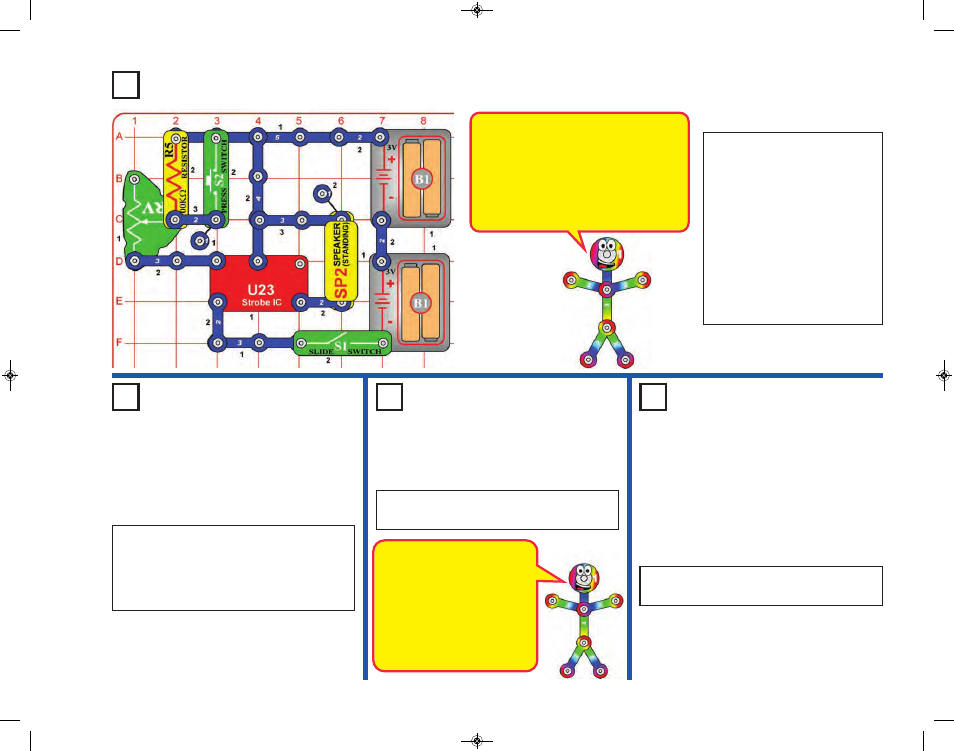
Project 19
Sound Maker
Project 20
Strobe Light
Project 21
Color Strobe
Light
Project 22
Red Strobe
Light
The color LED will not be
changing colors like it does in
other circuits. When the strobe
IC (U23) turns the color LED
on and off, it resets the color-
control microcircuit in the color
LED. Even your slowest strobe
speed is too fast for the color
LED.
Build the circuit and turn on the
switch (S1). You hear sound from
the speaker. Adjust the sound
using the lever on the adjustable
resistor (RV), and by pushing the
press switch (S2).
Note: In rare cases the circuit
may not work at all settings on
RV. If this happens, move the RV
lever to the side near the strobe
IC, turn the slide switch off and on
to reset the circuit, and only move
the RV lever over a small range.
The strobe IC (U23) produces an
electrical “tone”. The pitch of the “tone” is
adjusted by changing how much electricity
flows into its upper-left snap, using a
resistor. The electrical tone it produces
can be used to make sound using a
speaker, or to control the flash rate of an
LED see project 20, the Strobe Light).
Use the preceding circuit, but replace the
speaker with the white LED (D6). Now you
have a strobe light!
When S2 is pressed, the light may be blinking
so fast that it appears to be on continuously.
Use the preceding circuit, but replace the white
LED with the color LED (D8).
Use the preceding circuit but replace the color
LED (D8) with the red LED (D1).
SCC-350_Manual_Part_A.qxp 7/25/14 2:40 PM Page 41