Project 47 strobe effects, Project 48 slow strobe effects – Elenco Snap Circuits® Deluxe Sound & Light Combo User Manual
Page 50
-49-
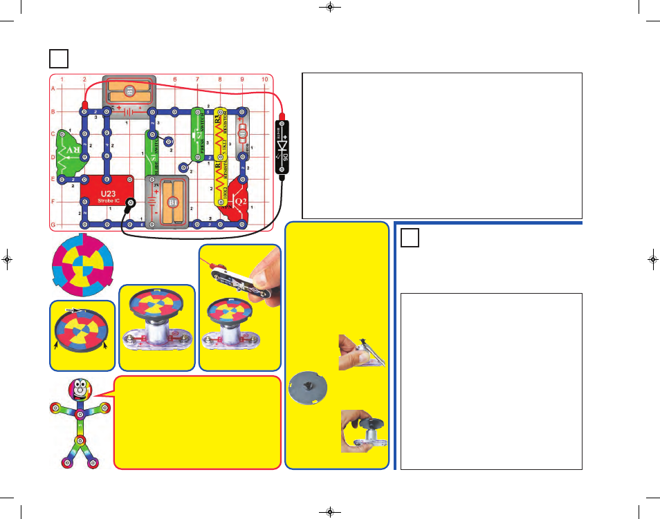
Project 47
Strobe Effects
Project 48
Slow Strobe
Effects
Tab
Slide tabs into slots.
Tab
Tab
Place disc holder onto
the motor as shown.
Hold white LED (D6)
over disc as shown.
How does this work? The strobe IC is making the
white LED flash so fast that your eyes think it is on
continuously. RV sets the flash rate, and at some
settings the LED flashes are synchronized with
speed of the patterns spinning on the disc, making
them appear visible instead of blurred.
When the disc pattern is totally blurred, it will appear
as purple, orange, and light green. Combining equal
amounts of red & blue makes purple, red & yellow
makes orange, and yellow & blue makes green.
OPTIONAL
(Adult supervision required)
The disc holder rests on the motor top
loosely and vibrates, making the disc
pattern blurry even when the RV setting
makes the pattern “stop”. The disc
patterns will appear clearer if you
permanently mount the disc holder to the
motor top. This set contains a spare
motor top, which can be used for this.
This requires removing the motor top
from the motor whenever you want to
switch from using the disc holder to
using the glow fan, so is optional, and
requires adult supervision.
If you want to do
this, pry the motor
top off the motor
shaft
using
a
screwdriver.
Lay the spare motor
top in the disc holder
upside down, and bond
together with glue (glue
not included).
After the glue dries,
push the modified
disc holder on the
motor shaft and
install a disc cutout.
When you want to
return to using the
glow fan, replace the motor top disc
holder with the normal motor top.
Build the circuit as shown. Take the colored disc shown and install it into the disc holder,
then place the disc holder on the motor (M1). Connect the white LED (D6) to the red &
black jumper wires.
For best effects, do this in a dimly lit room. Turn on the slide switch (S1). Push the press
switch (S2) until the motor spins continuously (if it stops after you release the press
switch, replace your batteries). Hold the white LED upside down over the disc holder so
it shines on the spinning disc, and move the lever on the adjustable resistor (RV) slowly
while watching the pattern on the spinning disc.
The motor spins the disc so fast that it looks like a blur. However, as you slowly adjust
RV the pattern on the disc appears to slow down, stop, and reverse direction. Patterns
close to the disc center may be moving at different speeds, or in different directions, from
patterns farther from the center! Some patterns may become clear while others are still
blurred.
If the motor does not continue spinning after you release S2, then replace your batteries. If
it still won’t keep spinning then replace the 5.1kW resistor (R3) with a 3-snap wire.
Use the preceding circuit, but replace the 3-snap on the
adjustable resistor (RV) with the 100kW resistor (R5).
The circuit works the same, but the strobe rate is much
slower (now you can see the LED flashing), so the strobe
effects are different. Slowly adjust the setting on RV as
before, and watch the patterns on the spinning disc.
Note: In rare cases the LED may not flash at all settings
on RV. If this happens, move the RV lever to the side
near the strobe IC, turn the slide switch off and on to
reset the circuit, and only move the RV lever over a small
range.
Bonus for owners of other Snap Circuits
®
sets:
If you
have a second 100kW resistor (from model SC-100 / 300
/ 500 / 750 or other sets), place it directly over the R5
that replaced the 3-snap in the above circuit (and place
a 1-snap under one side of the additional R5). Stacking
the two 100kW resistors together creates a “medium”
range of strobe speeds, in between the speeds created
with the 3-snap and single 100kW. Adjust the RV setting
and watch the strobe effects as before.
SCC-350_Manual_Part_A.qxp 7/25/14 2:40 PM Page 50