Elenco Snap Circuits® Deluxe Sound & Light Combo User Manual
Page 151
-150-
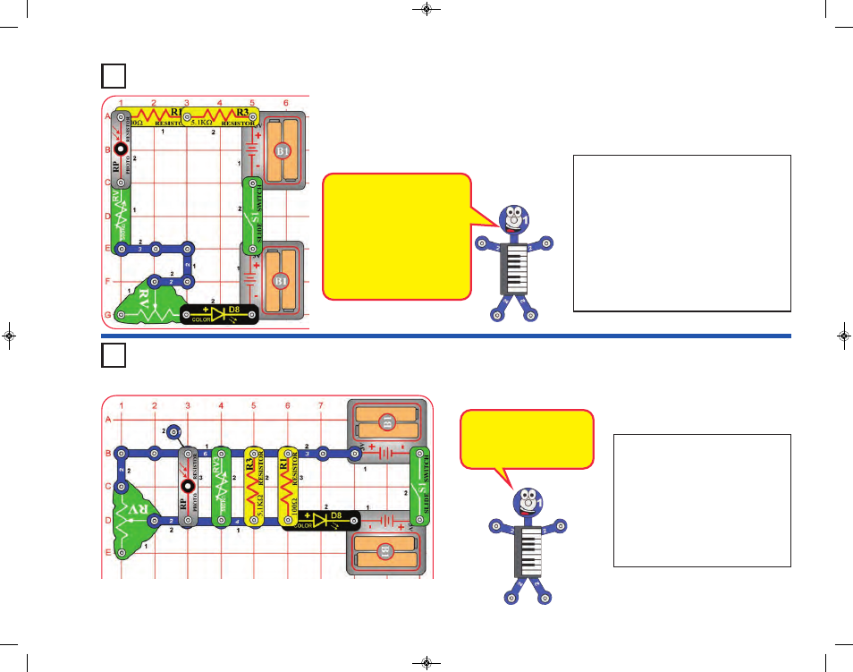
Turn on the right slide switch (S1).
There are five resistors (R1, R3, RV,
RV3, and RP), connected in parallel,
that are controlling the current to the
color LED (D8). See which resistor
has the most effect on the LED
brightness, by removing them one at
a time. The resistance of RV and RV3
depends on their setting, so try them
at different settings.
These five resistors are all
connected in parallel, so the
smallest one (R1, 100W),
will have the most effect.
Turn on the slide switch (S1). There are five
resistors (R1, R3, RV, RV3, and RP),
connected in series, that are controlling the
current to the color LED (D8). See which
resistor has the most effect on the LED
brightness, by replacing them with a 3-snap
wire or the red/black jumper wires, one at a
time. The resistance of RV and RV3 depends
on their setting, so try them at different
settings. Note that the photoresistor’s (RP’s)
resistance can be very high if there isn’t bright
light shining on it.
Project 358
Lots of Resistors in
Series
Project 359
Lots of Resistors in
Parallel
These five resistors are all
connected in series, so the
highest value, will have the
most effect.
Swapping the locations of any
parts in the circuit (without
changing the direction of their
“+” side) will not change how
the circuit works. Try it.
SCC-350_Manual_Part_C.qxp 7/25/14 2:11 PM Page 39