Advanced troubleshooting, Adult supervision recommended) – Elenco Snap Circuits® Deluxe Sound & Light Combo User Manual
Page 24
-23-
Advanced Troubleshooting
(Adult supervision recommended)
ELENCO
®
is not responsible for parts
damaged due to incorrect wiring.
If you suspect you have damaged parts,
you can follow this procedure to
systematically determine which ones need
replacing:
(Note: Some of these tests connect an LED directly
across the batteries without another component to
limit the current. Normally this might damage the
LED, however Snap Circuits
®
LEDs have internal
resistors added to protect them from incorrect
wiring, and will not be damaged.)
1.
Red LED (D1), motor (M1), speaker
(SP2), and battery holder (B1):
Place
batteries in holder. Place the red LED
directly across the battery holder (LED + to
battery +), it should light. Do the same for
the motor, it should spin. “Tap” the speaker
across the battery holder contacts, you
should hear static as it touches. If none
work, then replace your batteries and
repeat. If still bad, then the battery holder
is damaged.
If the motor spins but does not balance the
fan, check the black plastic piece with three
prongs on the motor shaft, and replace it if
it is damaged (this kit includes a spare). To
replace, pry the broken one off the motor
shaft using a screwdriver, then push the
new one on.
2.
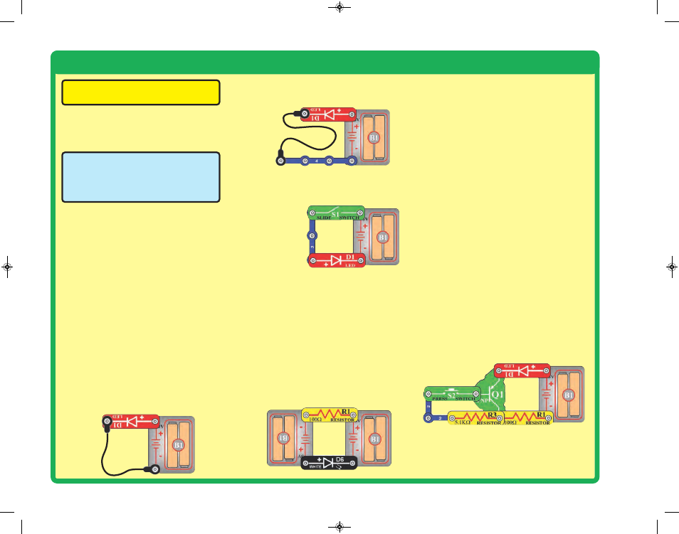
Red & black jumper wires:
Use this mini-
circuit to test each jumper wire, the LED
should light.
3.
Snap wires:
Use this mini-circuit to test
each of the snap wires, one at a time. The
LED should light.
4.
Slide switch (S1) and Press switch (S2):
Use this mini-circuit; if the LED doesn’t light
then the slide switch is bad. Replace the
slide switch
with the press
switch to test it.
5.
100W (R1) and 5.1kW (R3) resistors:
Use
the mini-circuit from test 4 but replace the
switch with the 100W resistor (R1); the LED
will be bright if the resistor is good. Next
use the 5.1kW resistor in place of the 100W
resistor; the LED should be much dimmer
but still light.
6.
White LED (D6) and color LED (D8):
Use
this mini circuit; if the white LED doesn’t
light then D6 is bad. Replace the white LED
with the color LED; it should change colors
in a repetitive pattern, otherwise D8 is bad.
7.
500kW adjustable resistor (RV3),
Microphone (X1), Photoresistor (RP),
and Phototransistor (Q4):
Use the mini-
circuit from test 6 but replace the 100W
resistor with RV3. Turning RV3’s knob all
the way to the left (counter-clockwise)
should make the LED dim or off; otherwise
RV3 is bad. Next, replace RV3 with the
microphone (+ on right); if blowing into the
microphone does not change the LED
brightness then X1 is bad. Next, replace
the microphone with the photoresistor (RP)
or phototransistor (Q4, + on right). Waving
your hand over the RP/Q4 (changing the
light that shines on it) should change the
brightness of the LED or that part (RP or
Q4) is bad.
8.
Adjustable resistor (RV):
Build project
160, but use the red LED (D1) in place of
the color LED (D8). Move the resistor
control lever to both sides. When set to
each side, one LED should be bright and
the other off (or very dim); otherwise RV is
bad.
9.
PNP transistor (Q1):
Build the mini-circuit
shown here. The red LED (D1) should only
be on if the press switch (S2) is pressed. If
otherwise, then Q1 is damaged.
SCC-350_Manual_Part_A.qxp 7/25/14 2:39 PM Page 24