Elenco Snap Circuits® Deluxe Sound & Light Combo User Manual
Page 102
-101-
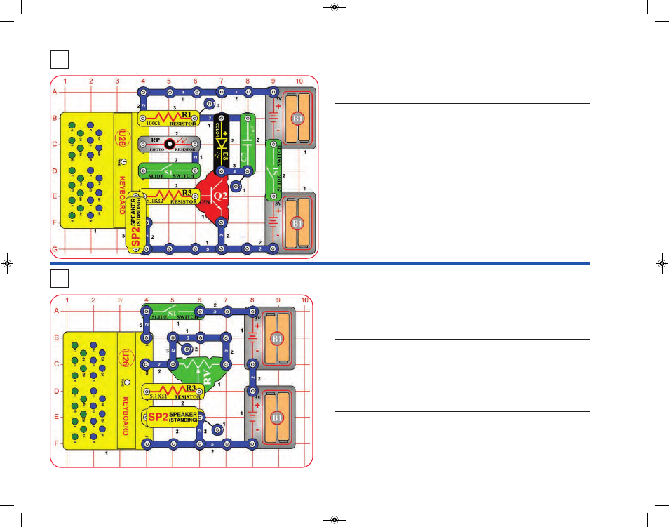
Project 199
Light & Sound
Project 200
See Saw
Build the circuit as shown; note that a 2-snap wire is placed directly
under the speaker (SP2). Turn off the left slide switch (S1) and turn on
the right slide switch. Press keys on the keyboard (U26) to make sound
on the speaker (SP2) and light on the color LED (D8). If you hold a key
down then the color LED will change colors.
Now turn on the left slide switch. If there is light on the photoresistor
(RP), or if you press keys on the keyboard, then there will be sound
from the speaker and light from the color LED. Wave your hand over
the photoresistor to change the sound, or turn off left S1 to disable
photoresistor control. Holding a key down will also make the color LED
change colors.
Turn on the slide switch (S1), and move the lever on the adjustable
resistor (RV) around. The pitch of the sound will be lowest with the lever
in the middle position, and higher with it set to the left or right.
You can replace the 5.1kW resistor (R3) with the 100W resistor (R1) or
500kW adjustable resistor (RV3), but there may be no sound at some
settings.
SCC-350_Manual_Part_B.qxp 7/25/14 2:06 PM Page 46