Elenco Snap Circuits® Deluxe Sound & Light Combo User Manual
Page 42
-41-
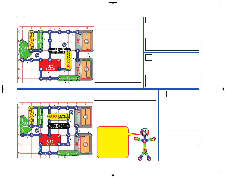
Project 23
Noisy Strobe Light
Project 26
Louder Strobe Light
Project 24
Noisy Red
Strobe Light
Project 25
Double
Strobe Light
Project 27
Louder Color
Strobe Light
This circuit is louder
than the previous
circuits because the
speaker is in parallel
with the LED instead of
in series with it. This
increases the voltage
across the speaker,
making it louder.
Modify the project 19 circuit to be this
one, which has the white LED (D6)
next to the speaker (SP2). Build the
circuit and turn on the switch (S1).
Adjust the blink rate and sound using
the lever on the adjustable resistor
(RV), and by pushing the press
switch (S2).
Note: In rare cases the circuit may
not work at all settings on RV. If this
happens, move the RV lever to the
side near the strobe IC, turn the slide
switch off and on to reset the circuit,
and only move the RV lever over a
small range.
Use the preceding circuit but replace the
white LED (D6) with the red LED (D1) or
the color LED (D8).
Use the preceding circuit but replace the
speaker and LED with any two LEDs (red,
white, or color).
Modify the preceding circuit to be this one, which
has the white LED (D6) in parallel with the speaker
(SP2). Build the circuit and turn on the switch (S1).
Adjust the blink rate and sound using the lever on
the adjustable resistor (RV), and by pushing the
press switch (S2).
Use the preceding circuit but
replace the white LED (D6)
with the red LED (D1) or the
color LED (D8).
SCC-350_Manual_Part_A.qxp 7/25/14 2:40 PM Page 42