Project 378 fiber optic echo, Project 379 fiber strobe echo – Elenco Snap Circuits® Deluxe Sound & Light Combo User Manual
Page 159
-158-
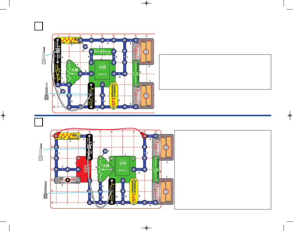
Build the circuit as shown. Place the clear cable holder on the white LED
(D6) and the black cable holder on the phototransistor (Q4), then place the
fiber optic cable into the holders as far as it will go. For best performance
the cable should stand straight up in the holders, without bending them.
Turn on slide switch (S1) and you hear weird sounds from the speaker
(SP2). Move the lever on the adjustable resistor (RV) around and see
if you can notice a difference in the echoes.
Project 378
Fiber Optic Echo
Black
Clear
Build the circuit as shown. Place the clear cable holder on
the white LED (D6) and the black cable holder on the
phototransistor (Q4), then place the fiber optic cable into the
holders as far as it will go. For best performance the cable
should stand straight up in the holders, without bending them.
Turn on the slide switch (S1) and vary the amount of light
shining into the photoresistor (RP). You hear sound from the
speaker (SP2). Move the lever on the adjustable resistor (RV)
around to vary the amount of echo on the sound.
Note: The circuit may not work at low light levels on RP. If
this happens, increase the light to RP, and turn the slide
switch off and on to reset the circuit.
Try replacing the photoresistor with the 500kW adjustable
resistor (RV3) and move its knob to adjust the sound, but
there will only be sound over the leftmost of RV3’s adjustment
range. If the circuit stops working, set RV3’s knob to the far
left, and turn the slide switch off and on to reset the circuit.
Project 379
Fiber Strobe Echo
Black
Clear
SCC-350_Manual_Part_C.qxp 7/25/14 2:11 PM Page 47