Project 217 optical echo in stereo, Project 218 color short light – Elenco Snap Circuits® Deluxe Sound & Light Combo User Manual
Page 109
-108-
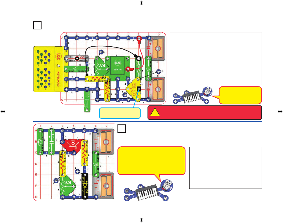
Headphones or Stereo
Speaker (not included)
The 0.1mF capacitor (C2) is
being used as a spacer (a
1-snap wire) to support
other components.
WARNING:
Headphones performance varies, so use caution. Start with
low volume, then carefully increase to a comfortable level. Permanent
hearing loss may result from long-term exposure to sound at high volumes.
!
The project is similar to the preceding one, but adds optical
control using the photoresistor (RP). Rebuild the preceding
circuit to match this one. Follow the preceding circuit’s
instructions, except also turn on the slide switch next to the
photoresistor, and then wave your hand over the
photoresistor to change the sound.
The keyboard overhangs the base grid, so be sure the
connections to it stay secure as you are pressing keys.
In the preceding circuit you could add the 1mF capacitor (C7)
to make the echo sound louder, but do not have enough
parts to add it to this circuit.
Build the circuit, turn on the slide switch (S1),
and push the press switch (S2). The color LED
(D8) is on for a while and then shuts off.
Turning S1 off and back on will not get the light
back on. Push S2 to get the light back on. If
desired, place the egg attachment on the color
LED.
RV is used as a fixed resistor (50kW); so
moving its control lever will have no effect.
Project 217
Optical Echo in Stereo
1
Project 218
Color Short Light
The light is on while the 470mF capacitor
(C5) is charging, and shuts off when the
capacitor gets fully charged. Pressing S2
discharges the capacitor. The charge-up
time is set by the capacitor’s value and
resistors R3 and RV.
SCC-350_Manual_Part_B.qxp 7/25/14 2:06 PM Page 53