About your snap circuits, Parts, Transistors – Elenco Snap Circuits® Deluxe Sound & Light Combo User Manual
Page 11: Electronic modules, Leds
-10-
About Your Snap Circuits
®
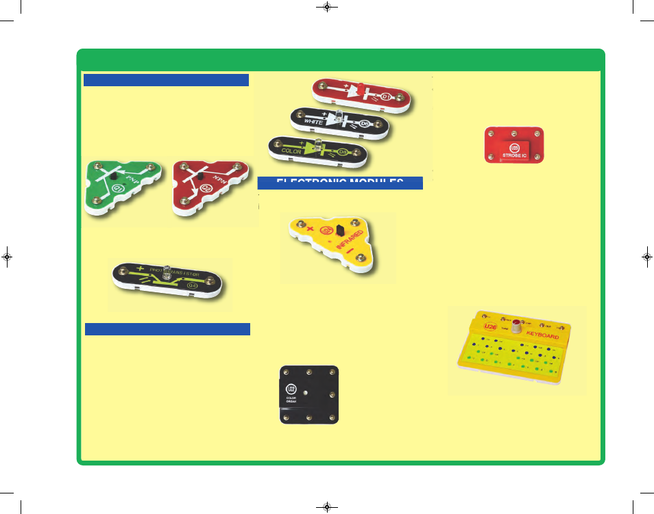
Parts
TRANSISTORS
The phototransistor (Q4) is a transistor that
uses light to control electric current.
Phototransistor (Q4)
ELECTRONIC MODULES
(+)
NC
OUT
(–)
CTL
Connections:
(+) - power from batteries
(–) - power return to batteries
OUT - output connection
CTL - strobe speed control
NC - not used
See project 47 for example of proper connections.
B
(+)
FB
Connections:
R - red color control
G - green color control
B - blue color control
(+) - power from batteries
INP - circuit input
FB - feedback connection
(–) - power return to batteries
IN - audio input jack
OUT - audio output jack
See projects 5, 6, 33,
and 35 for examples
of proper connections.
INP
(–)
G
R
The
color organ (U22)
contains resistors,
capacitors, transistors, a tri-color LED, and
integrated circuits. The LED in it can change
colors by direct control, or in synch with an audio
input signal. A schematic for it is available at
www.snapcircuits.net/faq.
OUT
IN
The
strobe IC (U23)
contains resistors,
capacitors, and transistors that are needed to
make a strobe light circuit. A schematic for it is
available at www.snapcircuits.net/faq.
Infrared module (U24)
The
Infrared module (U24)
is a miniaturized
infrared receiver circuit for remote control.
The
PNP & NPN transistors (Q1 & Q2)
are
components that use a small electric current to
control a large current, and are used in switching,
amplifier, and buffering applications. They are
easy to miniaturize, and are the main building
blocks of integrated circuits including the
microprocessor and memory circuits in computers.
PNP & NPN Transistors (Q1 & Q2)
LEDs
LEDs
(D1, D6, & D8)
The red, white, and color LEDs (D1, D6, & D8)
are light emitting diodes, and may be thought of
as a special one-way light bulbs. In the “forward”
direction, (indicated by the “arrow” in the symbol)
electricity flows if the voltage exceeds a turn-on
threshold (about 1.5V for red, about 3.0V for
white, and in between for other colors);
brightness then increases. The color LED
contains red, green, and blue LEDs, with a micro-
circuit controlling then. A high current will burn
out an LED, so the current must be limited by
other components in the circuit. LED’s block
electricity in the “reverse” direction.
The keyboard (U26) contains resistors,
capacitors, switches, and an integrated circuit. It
can produce two adjustable audio tones at the
same time. The tones approximate musical notes,
and may not be exact. The tone of the green keys
can be adjusted with the tune knob or using
external resistors and capacitors. A schematic for
it is available at www.snapcircuits.net/faq.
Connections:
(+) - power from batteries
RES - resistor freq adjust
CAP - capacitor freq adjust
OUT - output connection
(–) - power return to batteries
See projects 186, 191, & 210 for example of proper
connections.
Keyboard (U26)
SCC-350_Manual_Part_A.qxp 7/25/14 2:39 PM Page 11