Section 9.4- engine control circuit, Engine control circuit board, Page 9.4-1 – Generac 86640 User Manual
Page 92
Attention! The text in this document has been recognized automatically. To view the original document, you can use the "Original mode".
Section 9.4- ENGINE CONTROL CIRCUIT
Engine Control Circuit Board
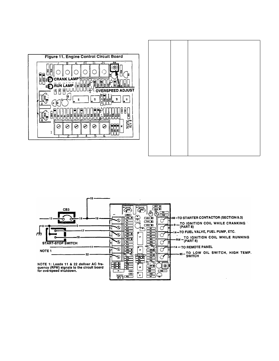
An engine control circuit board (Figure 11), noused in the
generator control panel, controls engine starting, running and
shutdown functions. A 12 volts DC power supply is delivered
to the board for control of those functions.
Circuit board terminals, connecting wires and a descrip
tion (or function) of the wires is listed in the following chart:
TERMINAL
WIRE
DESCRIPTION OR FUNCTION
1
15
Breaker protected 12 volts DC power
to operate engine control system.
2
0
Common ground.
3
17
Engine will crank when this circuit
is grounded.
4
18
Engine will shut down when this
circuit is grounded.
5&6
11, 22
Frequency (engine speed) signals
from generator AC power leads for
automatic engine shutdown.
7
56
Crank signal- starter contactor
energizes when circuit board
energizes Wire 56 circuit.
8
9
Delivers 12 volts DC to ignition
coil for engine cranking only.
9
14
Delivers 12 volts DC to carburetor
fuel valve, fuel pump and DC alter
nator for running.
10
RW
Once cranking has ended, battery
power Is delivered to the Ignition
coil via a resistance wire.
11
14
Delivers 12 volts DC to a
remote panel only when the
engine is running.
12
85
When this circuit Is grounded by
closure of either (a) a low oil
pressure switch, or (b) a high
coolant temperature switch, an
automatic engine shutdown will
occur
Figure 12. Engine DC Control Circuit
Page 9.4-1