Valve inserts, Camshaft bearing clearance – Generac 86640 User Manual
Page 35
Attention! The text in this document has been recognized automatically. To view the original document, you can use the "Original mode".
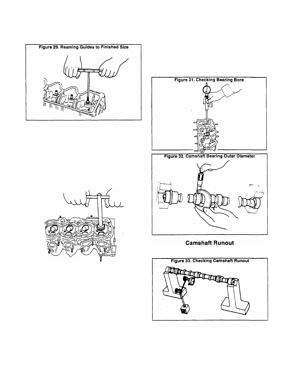
5. Ream the valve guides to a finished size of 0.2758-0.,2764
inch (7.005-7.020mm).
Valve Inserts
Inspect valve inserts for evidence of pitting at valve
contact surfaces. Reseat or replace, if worn or pitted exces
sively. The following rules apply:
D When repairing valve inserts, first check the valve and
valve guide for wear. If worn, replace them. Then, correct
the valve seat.
□ When cutting, use both hands for more uniform cutting.
Figure 30.
If necessary, replace valve inserts as follows:
1. Ream the cylinder head recess.
2. Heat the cylinder head to 302‘-320’ F. (150'-160‘ C.).
3. Install the insert. Make sure it bends at bottom face of its
recess and caulk at more than 4 places.
4. Use a suitable tool to grind newly fitted valve seats. Grind
the seats to the specifications listed in the applicable SPEC
IFICATIONS chart.
5. Apply a small amount of valve grinding compound to the
valve contacting face and place valve into guide.
Camshaft Bearing Clearance
Check camshaft bearing clearance (Figure 31). Check
both the bore and the bearing outside diameter (O.D.). The
difference between the two measurements is the bearing
clearance. Maximum bearing clearance is shown below:
MAXIMUM CAMSHAFT BEARING CLEARANCE
0.0059 Inch (0.15mm)
Use a suitable measuring device to check camshaft
runout (Figure 33).
Page 2.3-3