Starter contactor (continued), Starter, Description – Generac 86640 User Manual
Page 89: Starter motor servicing, Starter performance test, Battery, Recommended battery, Ba’ttery cables, Effects of temperature on battery
Attention! The text in this document has been recognized automatically. To view the original document, you can use the "Original mode".
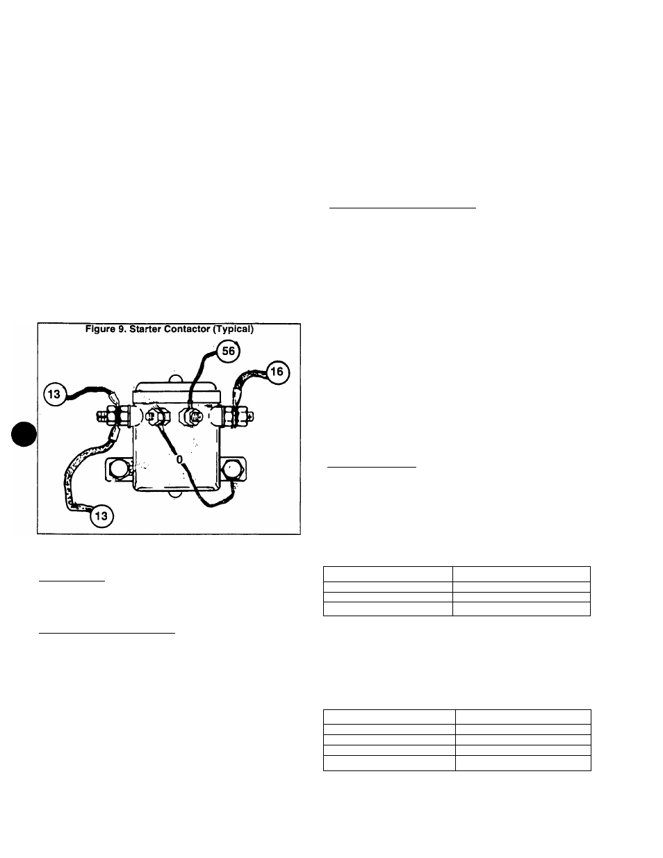
starter Contactor (Continued)
>
2. Connect the positive VOM test iead to the large contactor
terminal stud to which the starter cabie attaches and the
common VOM test iead to ground. Hold the start-stop switch
at “Start“ and battery voltage should be indicated,
a. If normal battery voltage is indicated, but engine does
not crank, check the contactor to starter cable and the
starter itself.
b. If normal battery voltage is NOT indicated when the
start-stop switch is set to “Start“, go to Step 3.
3. Check for battery voltage at the small starter contactor
terminal to which Wire 56 attaches. When the start-stop
switch Is set to “Start" battery voltage should be indicated,
a. If batte^ voltage is indicated in Step 3 but was NOT
indicated in Step 2, check the starter contactor ground
wire. If ground wire is good, replace the starter contactor,
b. If battery voltage is NOT indicated in Step 3 when the
start-stop switch is set to "Start“, check the following:
(1) Wire 56 between the starter contactor and the engine
control circuit board.
(2) The start-stop switch.
(3) The 10 amp circuit breaker.
(4) Power supply to the engine control circuit board.
Starter
DESCRIPTION:
The starter assembly is shown in Figure 10. It is rated 12
volts DC. Never apply any voltage in excess of rated voltage
or magnets in the starter may become demagnetized.
STARTER MOTOR SERVICING:
1. Inspection: Check for adverse wear on all bearings,
gears, shafts, etc. Check the sprino washer for wear, convex
side next to bearing. Add a drop of oil to face of bearing.
2. Thru-Bolts: Tighten thru-bolts to 75 inch-pounds.
3. Drive Cap: Apply a film of SAE #10 oil to the bearings in
the drive cap. During reassembly, the insulating washer must
be placed against the drive cap.
4. Brush Assembly: Brushes and brush springs should be
replaced at each overhaul. Any brush that is worn to 5/16 inch
or less, measured on short side of brush, or that has been in
contact with grease, oil or cleaning fluid, must be replaced.
Assemble brushes with their chamfered side sway from the
springs. Tighten brush screw to 30-35 inch-pounds. Tighten
the hot stud nut to 45-50 inch-pounds.
5. Armature: Check the armature for an open, shorted or
grounded condition with a growler. Hold armature in a vise
while installing or removing the drive assembly. Apply a thin
film of non-conducting grease to the commutator end of the
armature shaft and to the portions of the shaft that contact
the bearings.
STARTER PERFORMANCE TEST:
CAUTION:
DO
NOT
operate
the
starter
continu-
ously for longer than 30 seconds. _____________________
Use a fully charged, 12 volts battery to test the starter.
Attach the battery’s positive terminal to the starter motor input
stud, and the battery negative terminal to the starter motor
housing. Use a No. 10 (or larger) cable not more than 6 feet
long. Maximum current draw and starter speed should be as
follows:
MAXIMUM NO-LOAD CURRENT DRAW & SPEED
17 amps at 6000-7200 rpm
Battery
RECOMMENDED BATTERY:
When anticipated ambient temperature will consistently
be above 32" F. (O’ C.), use a 12 volts, automotive type
storage battery rated at 70 amp-hours and capable of deliv
ering at least 360 cold cranking amperes.
If ambient temperatures will be below 32" F. (O’ C.), use
a 12 volts battery rated 95 amp-hours and having a cold
cranking capacity of 450 amps.
BA’TTERY CABLES:
Use of battery cables that are too small in diameter or
too long will result in excessive voltage drop. For best cold
weather starting, voltage drop between the battery and starter
should not exceed 0.12 volt per 100 amperes of cranking
current.
Select battery cables based on total cable length and
prevailing ambient temperatures. Generally, the longer the
cable and the colder the weather, the larger the required
cable diameter. The following chart applies:
CABLE LENGTH (IN FEET)
RECOMMENDED CABLE SIZE
R5r2
TTTB
RoTO
16-20
No. 000
EFFECTS OF TEMPERATURE ON BATTERY:
Battery efficiency is greatly reduced by a decreased
electrolyte temperature, because such low temperatures
have a decided numbing effect on the electrochemical action.
Under high discharge rates (such as cranking), battery volt
age will drop to much lower values in cold temperatures than
in warm temperatures. The freezing point of battery electro
lyte fluid is affected by the state of charge of the electrolyte.
SPECIFIC GRAVITY
FREEZING POINT
1.220
^3rT;"(-37' c. )
1.200
-SO' F. (-29' C.)
TTreo
ITTVi-IO' C.)
Page 9.3-2