Introduction, Delcotron series 10 si, Dc alternator description – Generac 86640 User Manual
Page 86: Dc alternator adjustments, Testing, General, Undercharged battery
Attention! The text in this document has been recognized automatically. To view the original document, you can use the "Original mode".
Section 9.2- THE "DELCO®" CHARGING SYSTEM
Introduction
Some industrial-mobile (IM) engine-generators may be
equipped with a ’Delcotron®“ battery charging system. This
system utilizes a belt driven DC alternator having an integral
DC voltage regulator.
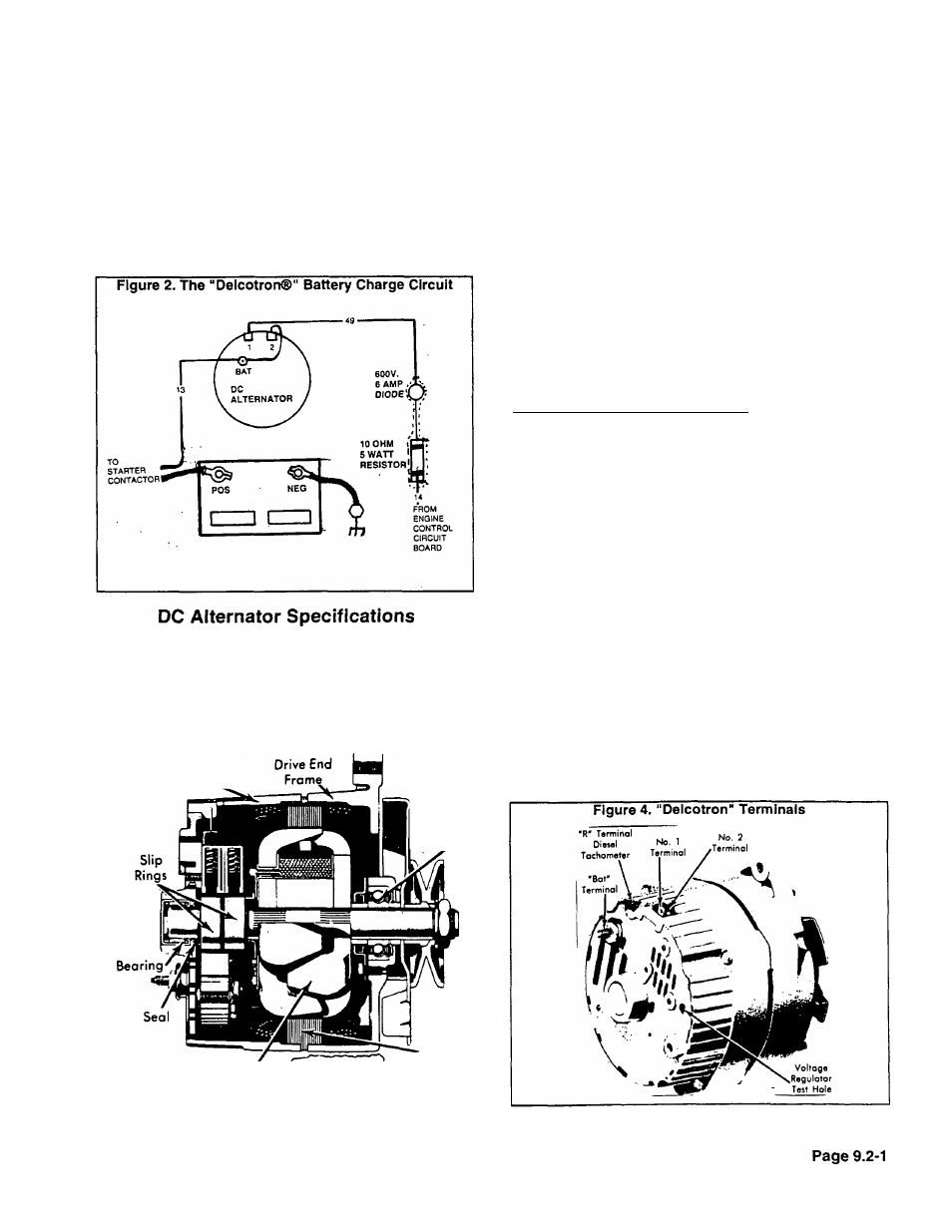
See Figure 2. During cranking and running operations,
an engine control circuit board delivers battery voltage to the
DC alternator via Wire No. 14, a resistor (R1) and a diode
(D1). This is DC alternator field excitation current. DC alter
nator output (charging) current is delivered to the battery via
Wire No. 13.
Delcotron Series................................................ 10 SI
System Voltage..................................................12
DELCO® Regulator No......................................1116392
Ground Polarity................................................... Negative
Figure 3. "Delcotron" DC Alternator
Slip Ring
End Frame
Bearing
Rotor
Stator
DC Alternator Description
See Figure 3. The DC alternator consists primarily of 2
end assemblies, rotor, stator, brushes, slip rings and diodes.
The rotor is supported in the drive end frame by ball bearings
and in the slip ring end frame by roller bearings. Bearings
contain sufficient lubricant to eliminate the need for periodic
lubrication.
DC Alternator Adjustments
No periodic adjustment or maintenance is required on
the DC alternator assembly. Regulator voltage is preset and
no regulator adjustment is needed.
CAUTION: Do NOT attempt to polarize the DC
alternator. Do NOT short or ground any terminals
except as Instructed. Never operate the DC alter
nator with battery out of circuit or with output
terminal open. The DC alternator and the battery
must share the same ground polarity.________________
Testing
GENERAL:
Beforte starting electrical checks, visually inspect all
terminals for clean and tight connections. Check DC alterna
tor mounting bolts and dnve belt tension. Do NOT ground the
No. 2 lead wire. Battery must be in good condition to test the
charging system.
UNDERCHARGED BATTERY:
1. Connect a DC voltmeter from the DC alternator “BAT"
terminal to ground (Figure 4). Crank the engine and nore the
meter reading. A “zero" reading indicates an open condition
between the “BAT“ connection and the engine control circuit
board.
a. If reading is “zero“ on gaseous fuel unit, test Wire 49
between DC alternator and diode (D1) for open. Check
diode (D1) and resistor (R1), as weil as Wire 14 for open.
b. If unit is a gasoline fueled unit and reading is "zero",
check Wire 49, diode (D1), resistor (R1) and Wire 14
between DC alternator and carburetor fuel valve for open.
Also check Wire 14, between carburetor fuel valve and
engine control circuit board, for open.