Test 9> check brushes and slip rings, Test 10- test main circuit breaker, Test 11- check ac power lead connections – Generac 86640 User Manual
Page 23: Test 12- test dpe circuit breaker
Attention! The text in this document has been recognized automatically. To view the original document, you can use the "Original mode".
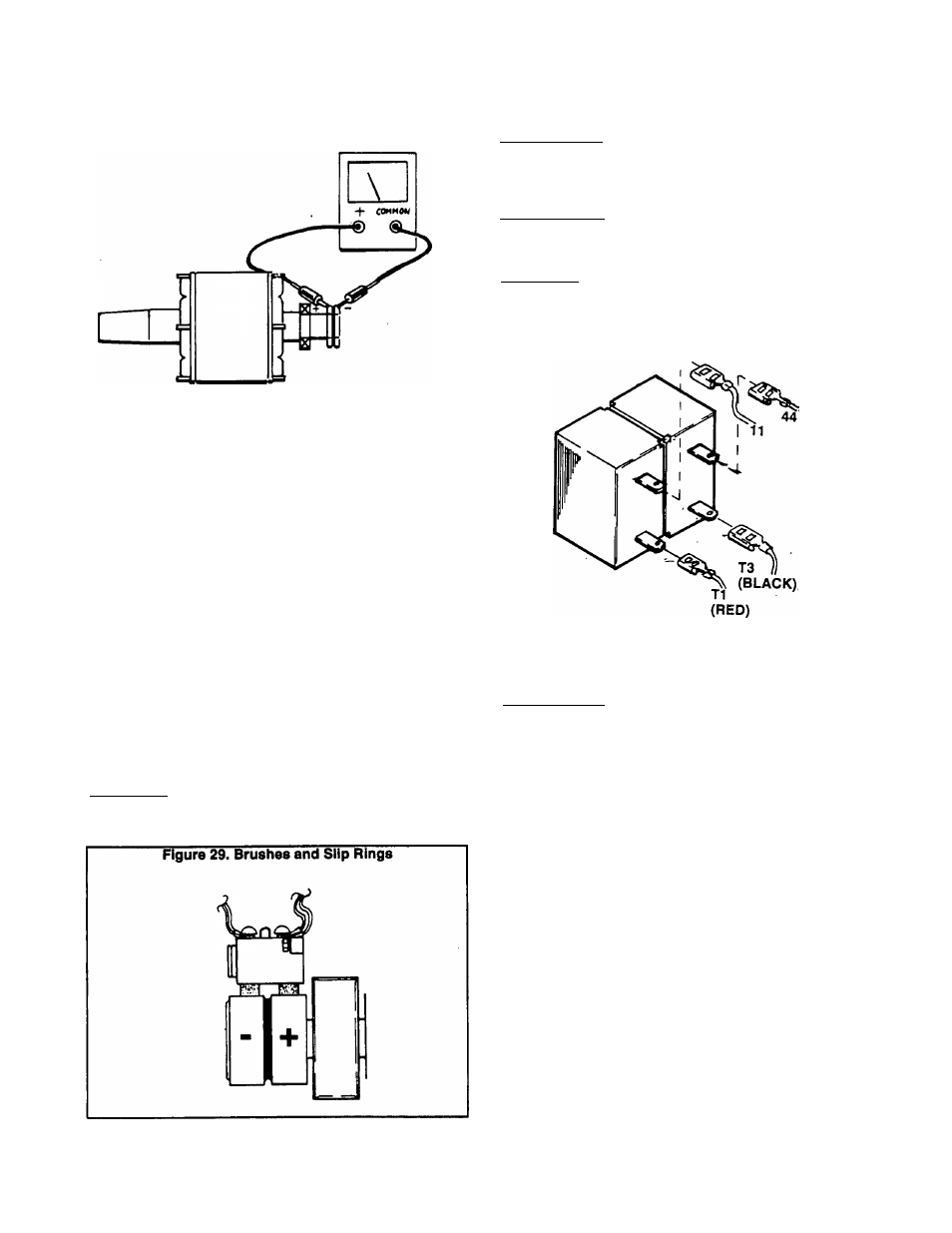
Figure 28. Checking Rotor Resistance
Test 9> Check Brushes and Slip Rings
DISCUSSION:
if the fixed (constant) excitation test did not result in an
AC output voitage of approximateiy one-haif rated voits, one
possibie cause of the probiem might be defective brushes
and/or slip rings.
PROCEDURE:
Remove Wires 1 and 4 from the brushes. Then, remove
the brush holders from the rear bearing carrier. Inspect the
brushes and brush holders. Replace, It cracked, damaged,
worn excessively, etc.
Inspect the slip rings. If they are dull or tarnished, they
can be cleaned with fine sandpaper. DO NOT USE ANY
METALLIC GRIT TO CLEAN SLIP RINGS. Use low pressure
air (25 psi or less) to blow away cleaning residue.
Reassemble brushes and brush holders to rear bearing
carrier. Make sure brushes are properly seated in brush
holders and are contacting the slip rings properly. Reconnect
Wires 1 and 4 to brushes. Rotate the Rotor several times to
seat the brushes against the slip rings.
RESULTS:
Clean slip rings, replace bad brushes or brush holder(s)
as necessary.
Test 10- Test Main Circuit Breaker
DISCUSSION:
■ If AC output voltage and frequency are "zero", one pos
sible cause of the problem is an open or failed main circuit
breaker.
PROCEDURE:
Make sure the main circuit breaker Is set to Its ’Closed’
position, if the breaker Is closed, check it for continuity.
RESULTS:
1. Replace main circuit breaker. If It Is defective.
2. If main breaker is good, go to Test 11.
Figure 30. Main Circuit Breaker (Typical)
Test 11- Check AC Power Lead Connec
tions
DISCUSSION:
The stator's AC output leads must be property connected
as outlined under ‘STATOR AC POWER CONNECTION
SYSTEMSr (Page 1.1-5).
PROCEDURE:
Check that Stator AC output leads 11,22,33 and 44 (as
well as T1, T2 and T3) are property connected as shown In
the appropriate wiring diagram/schematic. Reconnect wires
as necessary.
RESULTS:
Reconnect, repair or replace stator AC output leads as
necessary.
Test 12- Test DPE Circuit Breaker
DISCUSSION:
The excitation (DPE) circuit breaker is connected in
series with lead 2 (or 2A) between the stator excitation (DPE)
windings and the voltage regulator. If the breaker should
open, excitation winding AC output to the Regulator will be
lost and AC ou^ut from the generator will drop to a voltage
that is commensurate with the Rotor’s residual magnetism
(about 2 to 7 volts AC). Application of fixed excitation current
p est 6) will result in an AC output voltage equal to approxi
mately one-half rated voltage.
Page 1.6-3