Introduction, Generator disassembly, Inspection of major components – Generac 86640 User Manual
Page 11
Attention! The text in this document has been recognized automatically. To view the original document, you can use the "Original mode".
Section 1.2- MAJOR GENERATOR COMPONENTS
Introduction
This section will discuss generator disassembly, Inspec
tion of components, and reassembly. See Figure 21 on Page
1
.
2
-
2
.
Generator Disassembly
To disassemble the generator, proceed as follows. See
Figure 21.
1. Remove the four capscrews, lockwashers and flatwashers
(Items 22, 23 and 24) that retain the REAR BEARING CAR
RIER PLATE (Item 20) to the REAR BEARING CARRIER
(Item 15). Remove the REAR BEARING CARRIER PLATE
(Item 20).
2. Remove the Rear Bearing Carrier GASKET (Item 18).
3. Disconnect wires from BRUSH HOLDERS (Item 16).
4. Remove SCREWS (Item 17) that retain the BRUSH HOLD
ERS (Item 16) to the Rear Bearing CARRIER (Item 15).
Remove the BRUSH HOLDERS (Item 16).
5. Remove hardware that retains the Rear Bearing CARRIER
(Item 15) to the generator mounting base.
6. Remove the four long CAPSCREWS (Item 21), along with
four LOCKWASHERS (Item 10).
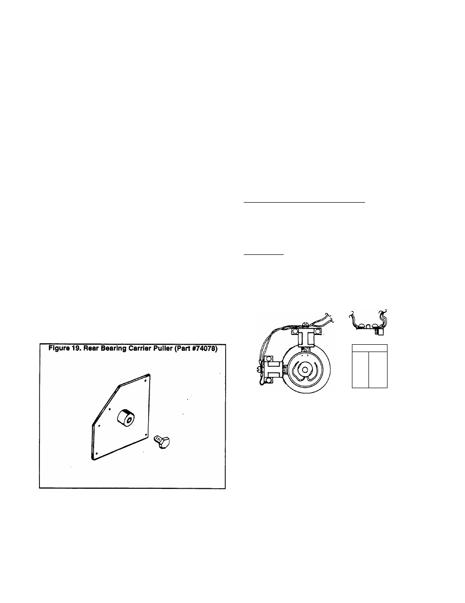
7. A REAR BEARING CARRIER PULLER tool Is available.
See Figure 19. To order the tool, specify Part No. 74078.
a. Retain the PULLER TOOL to the Rear Bearing CAR
RIER (Item 15) using the same M6-1.00 x 8mm screws
i
ltem 22) that were used to retain the Rear Bearing Carrier
»LATE (Item 20).
b. Turn the center bolt on the PULLER TOOL (Figure 19)
clockwise until the Rear Bearing CARRIER (Item 15) is
free of the Rotor bearing.
c. Completely remove the Rear Bearing CARRIER (Item
' 15).
8. Free the STATOR ASSEMBLY (Item 14) from the
BLOWER HOUSING (Item 2). Completely remove the STA
TOR ASSEMBLY (Item 14).
9. Remove the hardware that retains the STARTER (Item 40)
to the ENGINE PLATE (Item 29). Remove the STARTER.
10. Remove all fasteners that retain the BLOWER HOUSING
(Item 2). Remove the BLOWER HOUSING.
11. Remove CAPSCREWS (Item 33) that retain the FLEX
PLATE (Item 28) to the FAN & RING GEAR (Item 25).
12. Remove the ROTOR ASSEMBLY (Kern 1) with the FAN
& RING GEAR (Item 25) attached.
13. Remove CAPSCREWS and LOCKWASHERS (Items 34
and 36) that retain the FLEX PLATE (Item 28) to the engine
flywheel. Remove the FLEX PLATE (Item 28).
14. If the FAN & RING GEAR is to be removed from the
ROTOR (Item 1), proceed as follows:
a. Remove CAPSCREW and LOCKWASHER (Items 30
and 31) that retain the FAN & RING GEAR to the ROTOR.
b. Remove the SPACER (Item 27).
c. Remove the FAN & RING GEAR (Item 25) from the
ROTOR.
NOTE: The FAN & RING GEAR ASSEMBLY (Item 25) Is
retained to the ROTOR shaft by a KEY (Item 26).
Inspection of Major Components
REAR BEARING CARRIER Pj^TE:
Air slots in the Rear Bearing Carrier Plate allow cooling
air to be drawn into the generator by fan action during
operation. These air slots must be kept open and unob
structed. Clean the plate and check for cracks, obvious
damage. Replace the Plate, If necessary.
BRUSHES:
Inspect both Brush Holders and their Brushes. Look for
cracks, chipping, excessive wear. Replace any damaged
Brush Holder. Brushes should be replaced as a complete set.
Inspect Boish Leads No. 1 and 4, replace any damaged or
defective Brush Lead.
Figure 20. Brush Holders, Brushes and Leads
I
-
+
'
n-rf
BRUSH
HOLDER
SCREW
BRUSH WITH RED
LEAD CLOSEST
TO ROTOR BEARING
REAR BEARING CARRIER:
The Rear Bearing Carrier is an aluminum casting. Clean
the casting and blow dry with compressed air. Inspect care
fully for cracks, damage. An insert is pressed into the bearing
carrier center bore, to accept the Rotor bearing. Use an Inside
micrometer to check the diameter of the Insert. Replace the
Rear Bearing Carrier If its insert’s inside diameter (I.D.) is not
within the following limits:
2.384-2.386 Inches (71.996-72.012mm)
Page 1.2-1