Bearing clearance, Inspection (continued) – Generac 86640 User Manual
Page 42
Attention! The text in this document has been recognized automatically. To view the original document, you can use the "Original mode".
Inspection (Continued)
a. DO NOT turn the crankshaft or connecting rod when
Plastigage^ is being inserted.
b. When bearing clearance exceeds the specified limit,
check that the correct bearing has been installed. If exces
sive clearance still exists, use a thicker main bearing or an
undersize bearing to obtain correct clearance.
BEARING CLEARANCE
Main Bearing= 0.0012-0.0020 Inch (0.03-0.05mm)
Limit = 0.0030 inch (0.075mm)
Connecting
Rod Bearing= 0.0008-0.0024 Inch (0.02-0.06mm)
Limit = 0.0047 inch (0.12mm)
Figure 55. Checking Ring Gap
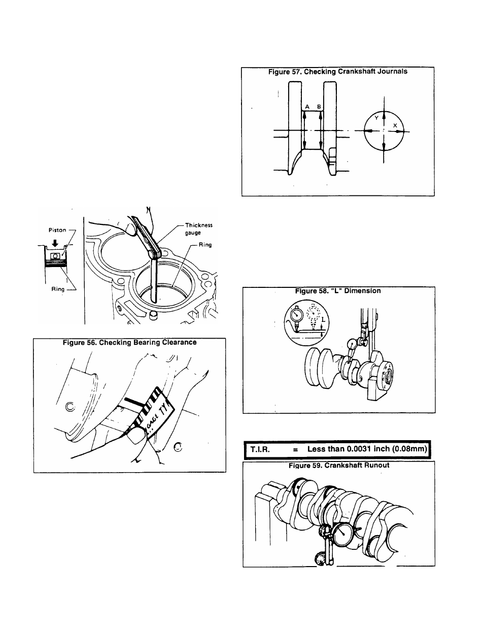
5. Inspect crankshaft journals for scoring, bias, wear or
cracks. Minor defects can be corrected using fine crocus
cloth. Use a micrometer to check journals for taper and
out-of-round. See Figure 57.
Out-of-Round (X-Y) = 0.0004 Inch (0.01mm)
Taper (A-B) = Less than 0.0008 inch (0.02mm)
6. When regrinding crankpin journal, measure the “L° dimen
sion in the fillet roll (Figure 58). The measured value must
exceed the specified limit. If measurements are within the
specified limit, DO NOT regrind.
NOTE: DO NOT grind off the fillet roll. Refer to applicable
SPECIFICATIONS chart for regrlndlng crankshaft and
available service parts.
7. Check crankshaft runout. “T.I.R." stands for "Total
Indicator Reading".
Page 2.6-2