Section 4.5- optional heat recovery system, General, Operation – Generac 86640 User Manual
Page 58: Customer remote heater, Exploded view of heat recovery system
Attention! The text in this document has been recognized automatically. To view the original document, you can use the "Original mode".
Section 4.5- OPTIONAL HEAT RECOVERY SYSTEM
General
Some IM (Industrial Mobile) engine-generators are
equipped with a heat recovery system. If desired, the cus
tomer can use this system to provide heated air while working
in cold areas (such as a manhole).
Operation
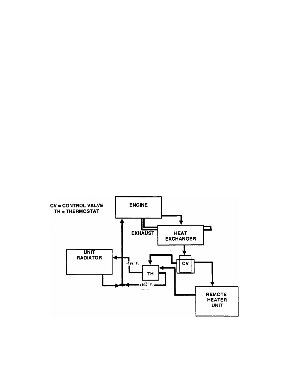
Figure 1, below, is a schematic diagram of a heat recov
ery system. Factory Installed components include (a) a heat
exchanger, fb) a control valve, (c) a thermostat, (d) the engine
radiator, and (e) interconnecting hoses and fittings. Operation
may be briefly described as follows;
1. Coolant from the engine flows through the heat exchanger
where it is heated by the engine exhaust, which also passes
through the heat exchanger.
2. From the heat exchanger, coolant flows to a control valve
(CV). The control valve can be positioned manually, as fol
lows:
a. It can be actuated manually to direct coolant through a
customer-supplied remote heater and then to a thermostat
housing (TH).
b. It can be actuated manually to direct coolant to the
thermostat housing (TH) and not to the customer’s remote
heater.
3. The thermostat (TH) either delivers the coolant back to the
engine or to the unit radiator, as follows:
a. If coolant temperature Is less than 192’ F. (89’ C.),
additional cooling is not needed, and the coolant Is deliv
ered back to the engine.
b. If coolant temperature is greater than 192’ F. (89’ C.),
additional cooling is needed, and the coolant is delivered
to the unit radiator and then back to the engine.
Customer Remote Heater
This heater is usually supplied by the user, in conjunction
with a fan or blower to extract the heat from the remote heater
and deliver it to the desired work area(s). The user must
ensure that the entire system has been properly filled with the
recommended coolant mixture prior to use.
Exploded View of Heat Recovery System
Figure 12 (next page) shows a typical heat recovery
system. Parts included in the drawing are iisted below.
ITEM DESCRIPTION
1
Exhaust Manifold
2
End Plate
3
Thermostat Hsng.
4
Thermostat
5
Gasket
6
Water Pump
7
Lockwasher
8
Hex Nut
9
Stud
10
Fitting
12
Pipe Plug
13
Gasket
14
Gasket
15
Gasket
16
Fitting
17
90* Fitting
18
Brass Fitting
19
Gasket
ITEM DESCRIPTION
20
Filler Neck
21
Radiator Cap
22
Exhaust Flange
23
Hose Clamp
24
Upper Hose
25
Lower Hose
26
Hose
27
Hose
28
Hose
29
Stud
30
Stud
31
Stud
32
Pipe Plug
34
Hose
35
Fitting
36
Hose Clamp
37
Lifting Lug
38
Lockwasher
Figure 11. Schematic Diagram- Engine Cooling and Heat Exchanger System
Page 4.5-1