Rotor rotational speed (continued), Relationship of voltage & frequency, Visuai inspection – Generac 86640 User Manual
Page 17: Constant excitation test
Attention! The text in this document has been recognized automatically. To view the original document, you can use the "Original mode".
Rotor Rotational Speed (Continued)
1. A 4-Pole Rotor must be operated at 1800 rpm to supply a
60 Hertz AC output frequency: or at 1500 rpm for a 50 Hertz
AC output frequency.
2. A 2-pole Rotor must be operated at 3600 rpm for a 60 Hertz
AC output frequency: or at 3000 rpm for a 50 Hertz frequency.
The following formulas apply to (a) frequency, (b) rpm, and
(c) number of Rotor poles:
FREQUENCY =
RPM
X
NO. OF ROTOR POLES
2 x 6 0
R P M o
2
X
60
X
FREQUENCY
NO. OF ROTOR POLES
NO. OF ROTO№
2
X
60
X
FREQUENCY
POLES
RPM
Relationship of Voltage & Frequency
The generator’s AC voltage regulator mounts a single
adjustable potentiometer, used for adjustment of tne
Regulator’s REFERENCE voltage (see ’EXCITATION S/S-
TEAf on Page 1.1-4). The potentiometer is called simly a
'Voltage Adjust Potentiometer* and is adjusted with the gen
erator running at no-load and at a specific operating speed.
It is important that the engine speed governor be properly
adjusted before the Voltage Adjust Potentiometer setting is
attempted. The no-load AC frequency and voltage settings
should be as follows:
1. For Units Rated 120/240 Volts at 60 Hertz: Set AC
frequency to 60.5-63.5 Hertz and Voltage to 121-127 volts
AC (line-to-neutral), or 242-254 volts AC (line-to-line).
2. For units rated 110/220 volts at 50 Hertz: Set AC fre
quency to 49-52 Hertz and voltage to 108-112 volts (line-to-
neutral).
Visuai inspection
Quite often problems that occur in the generator can be
detected by making a thorough visual inspection. Remove
covers and look for any obvious problems. Burned windings,
broken connections, leads, mounting brackets, etc., can usu
ally be Identified. Also look for loose or frayed insulation,
loose or dirty electrical connections, broken wires.
Verify that the generator AC output leads are properly
connected for (a) single voltage outpiut, or (b) dual voltage
output. See 'STATOR AC POWER CONNECTION SV%-
TEMSr on Page 1.1-5.
Check for any foreign objects, loose nuts, bolts, and
electrical connectors. Clear away paper, leaves, snow, build
ing materials, etc., that might be sucked into the generator.
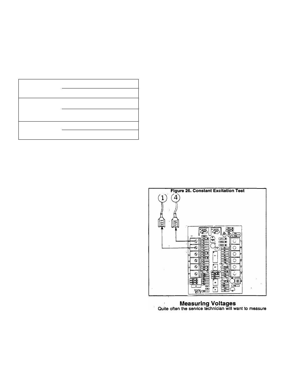
Constant Excitation Test
The generator’s AC output voltage will vary with Rotor
speed, generator design, connected loads, and excitation
current to the Rotor, if the generator speed and excitation
cunenttothe Rotor are known, the no-load AC output voltage
can be measured and compared to the design value. A
problem can be isolated to (a) Stator Excitation (OPE) wind
ings to Voltage Regulator circuit, including the Regulator, or
(b) Voltage Regulator to Rotor circuit, excluding the Regula
tor, or (c) the Stator assembly. Perform the test as follows:
1. Shut the generator engine down.
2. Connect a voltmeter to the generator’s AC output
leads.
3. Disconnect Wires No. 4 and 1 from the Voltage Reg
ulator.
4. Connect a jumper wire from terminal #1 (Wire #15) of
the engine control circuit board to the terminal end of Wire #4
(just disconnected from the Reguiator).
5. Connect a jumper wire from terminal #2 of the engine
control circuit board (Wire #0, ground) and to the terminal end
of Wire #1 Gust disconnected from the Regulator).
6. Start the generator and let It run at no-load (main
breakers open) and at its rated speed.
7. Read the generator’s AC output voltage from the
voltmeter connected In Step 2. Reading should be approxi
mately one-half rated voltage (about 40-60 volts line-to-neu-
tral or 80-120 volts line-to-line).
8. Shut the generator down.
9. Reconnect Wires No. 1 and 4 to the Voltage Regulator.
If voltage reading is normal in Step 7, the Wires #1 and
4 circuit, brushes and slip rings. Rotor and Stator are working
satisfactorily. The problem is In the circuit that Includes (a)
stator excitation windings, (b) thermal protector, (c)excitation
circuit breaker (CB4), (d) Wires 2 and 6, and (e) Voltage
Regulator.
NOTE: Field boost current la available to the Rotor only
while the engine Is cranking. Loss of excitation current
flow to the Rotor will result In a decrease In generator AC
output voltage to a value commensurate with Rotor re
sidual magnetism (about 2 to 7 volts AC),
a DC or AC voltage.
The DC voltage most often measured will be battery
voltage (12 volts DC).
When measuring AC voltages, the generator will have to
be running at rated speed and may have some of the protec
tive guárete and covers removed. BE CAREFUL. It is best to
shut the unit down when connecting meters. Use the meter’s
instruction manual to verify its operation and limitations.
Page 1.4-2