Introduction, Fuel solenoid assembly, Vaporizer-regulator assembly – Generac 86640 User Manual
Page 68: Carburetor assembly, Description, Adjustments
Attention! The text in this document has been recognized automatically. To view the original document, you can use the "Original mode".
Section 6.2- LIQUID WITHDRAWAL SYSTEMS
Introduction
Figure 8 (next page) is an Exploded View of a typical
LIQUID WITHDRAWAL type gaseous fuel system. Major
components of the system include the following:
D Fuel Solenoid Assembly,
n Vaporizer-Regulator Assembly,
n Carburetor Assembly.
D
Air Cleaner Assembly,
n Interconnecting lines and fittings.
Fuel Solenoid Assembly
See Item 12, Figure 8. The electrically actuated fuel
solenoid is energized open, de-energized closed. Mainte
nance on this part Is generally limited to replacement of the
entire solenoid assembly.
NOTE: If the fuel solenoid assembly must be replaced,
use only an assembly that Is useable with a liquid with
drawal system. Fuel solenoids are not Interchangeable
between liquid and vapor withdrawal systems. Fuel
solenoids used on liquid withdrawal systems must be
rated at a much higher pressure than vapor withdrawal
solenoids.
Vaporizer-Regulator Assembly
The vaporizer-regulator included with the Model 9052 LP
gas conversion kit is an IMPCO Model JB. The vaporizer-reg
ulator must perform the following functions:
n It must positively stop the flow of gas when the engine is
not running.
D At the slightest vacuum, the regulator metering valve
must move off its seat and allow gas flow to the engine,
n Heated engine coolant, passing through the vaporizer-
regulator, must vaporize the liquid fuel before it reaches
the carburetor.
See Figure 6. Engine coolant lines connect to the vapor
izer-regulator, as well as inlet and outlet lines for LP gas.
Figure 6. Vaporizer-Regulator
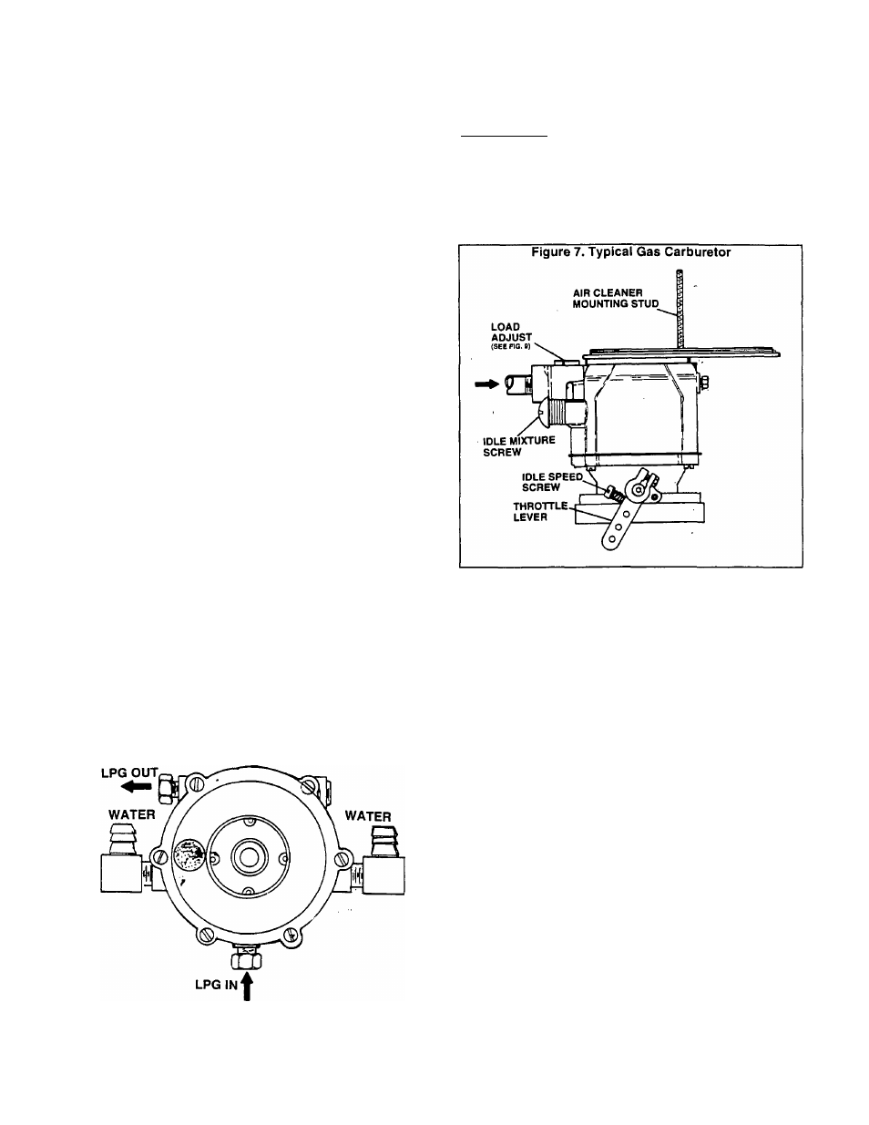
Carburetor Assembly
DESCRIPTION:
The carburetor assembly included with the Model 9052
gas conversion kit is an IMPCO Model CA50-506. See
Figure 7.
Vaporizer-regulator and carburetor operation are de
scribed under "GAS (^ARBURETION" on Page 6.1-2.
The carburetor is equipped with (a) an idle mixture ad
justment, and (b) a load adjustment.
ADJUSTMENTS:
Idle Mixture: This adjustment affects fuel-air mixture
only when the engine is running at idle speed. It has no affect
on operation at the engine’s normal rated speed of approxi
mately 1800 rpm and, for that reason, adjustment is not
required. However, if you wish to adjust idle mixture, proceed
as follows:
1. Connect an AC frequency meter to the generator’s AC
power output leads.
2. Disconnect all electrical loads from the generator.
3. Start the engine, let it stabilize and warm up at no-load.
4. Reduce engine speed until frequency meter reads approx
imately 30-33 Hertz.
5. Slowly turn the idle mixture screw clockwise until engine
starts to run rough. Then, turn the screw counterclockwise
until engine again starts to run rough. Finally, turn the screw
clockwise until smooth operation is obtained.
Load Adjustment: This is an adjustment of fuel-air
mixture with the rated load of the unit applied. Complete the
adjustment as follows:
1. Connect an AC frequency meter to the generator’s AC
power output leads.
2. Disconnect all electrical loads. This can be done by setting
the main circuit breaker to "Off“ or "Open".
3. See Figure 9. Turn the load adjustment as far as it will go
toward the "R" (maximum rich).
4. Start the engine, let it stabilize and warm up at no-load.
Page 6.2-1