Section 7.1- mechanical governor, General description, Governor maintenance – Generac 86640 User Manual
Page 74: Dc alternator removal, Governor lubrication, Engine governor adjustment
Attention! The text in this document has been recognized automatically. To view the original document, you can use the "Original mode".
Section 7.1- MECHANICAL GOVERNOR
General Description
The mechanical engine governor utilizes the principle of
spring tension versus centrifugal force to maintain a steady
state engine speed, regardless of the applied load. When
centrifugal flyweight force exceeds governor spring tension,
the flyweights act on a yoke to rotate a rocker shaft. Rocker
shaft rotation decreases carburetor throttle setting and en
gine speed decreases. As engine speed decreases, governor
spring tension becomes greater than flyweight centrifugal
force. The spring then increases carburetor throttle setting
and engine speed increases. The governed speed is that
rpm at which flyweight force and spring force are equal.
The governor flyweights are driven by an engine v-belt.
The pulley which drives the flyweights also dnves a DC
alternator assembly, used to maintain battery state of charge
during engine operation.
Figure 1. Mechanical Engine Governor
Governor Maintenance
Maintenance and repair of the governor is limited to the
following;
n Removal and replacement of the DC alternator assem-
bly.
□ Removal and replacement of governor lever, links and
springs.
D Removal, replacement and adjustment of governor to
carburetor linkage.
CH Adjustment of governed speed.
dC Alternator Removal
Refer to Figure 4 on next page. Remove the DC alterna
tor assembly as follows:
1. Remove hex jam nut (Item 43), wave washer (Item 48), and
pulley half (Item 44).
2. Remove the DC alternator Rotor (Item 44).
3. Remove socket head screws (Item 35) and lockwashers
(Item 22).
4. Remove the Stator (Item 47).
Reassemble the DC alternator in the reverse order of re
moval. Install socket head screws that retain the stator and
tighten them to 5 foot-pounds (7 N-m). Tighten the hex jam
nut to 35 foot-pounds (47 N-m).
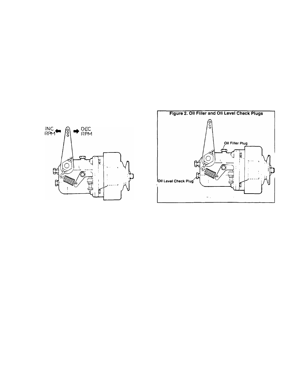
Governor Lubrication
See Figure 2. To fill the governor with oil, proceed as
follows:
1. Remove OIL FILLER PLUG and OIL LEVEL CHECK
PLUG,
2. Add engine oil through FILLER PLUG until oil just starts to
overflow the OIL LEVEL CHECK PLUG opening. Pour slowly.
3. When oil level is correct, install and tighten OIL FILLER
and OIL LEVEL CHECK PLUGS.
Engine Governor Adjustment
1. Connect an AC frequency meter across the generator’s AC
output leads.
2. Turn OFF all electrical loads. Initial adjustments will be
accomplished at no-load.
3. Start the engine, let it stabilize and warm up.
4. Check the no-load AC frequency. Readings should be as
follows:
Units Rated at 60 Hertz = 60.5-63.5 Hertz
Units Rated 50 Hertz = 49-51 Hertz
5. No-Load Governed Speed Adjustment: If adjustment of
no-load governed speed is required, proceed as follows (see
Figure 3):
a. Loosen the NO-LOAD BUMPER SCREW lock nut, then
loosen the NO-LOAD BUMPER SCREW so the governor
is not pre-loaded.
b. Adjust the NO-LOAD SPEED ADJUST SCREW to ob
tain a frequency reading as close as possible to 61.5 Hertz
for units rated 60 Hertz; or to 50.0 Hertz for units rated 50
Hertz.
c. Adjust the NO-LOAD BUMPER SCREW to obtain a
frequency of 62 Hertz (60 Hertz units); or 51 Hertz (50 hertz
units).
6. Adjustment Under Load: Apply an electrical load to the
generator equal to the rated wattage/amperage capacity of
the generator. Then, proceed as follows:
Page 7.1-1