Introduction, Fuel solenoid assembly – Generac 86640 User Manual
Page 71
Attention! The text in this document has been recognized automatically. To view the original document, you can use the "Original mode".
Section 6.3- VAPOR WITHDRAWAL SYSTEM
Introduction
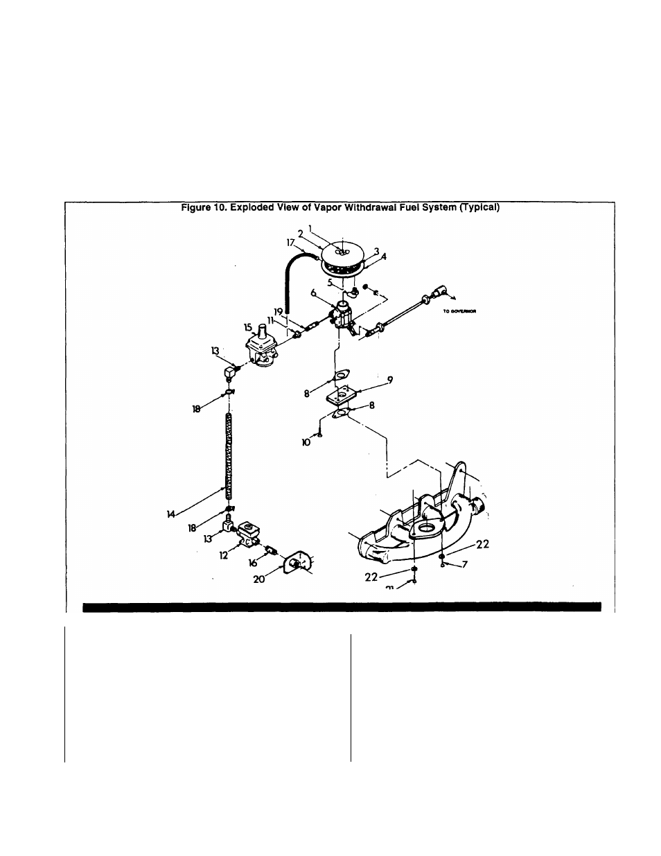
Figure 10 (below) is an Exploded View of a typical
VAPOR WITHDRAWAL type gaseous fuel system. Major
components include the following;
D Fuel Solenoid Assembly.
CH
Pressure Reducer Valve.
D
Carburetor Assembly.
D Air Cleaner.
n Interconnecting lines and fittings.
Fuel Solenoid Assembly
The electrically actuated fuel solenoid is energized open,
de-energized closed. Maintenance is generally limited to
replacement of the solenoid assembly. When replacing the
solenoid be sure to use the correct one for the system.
Solenoids are not interchangeable between liquid and vapor
withdrawal systems.
The solenoid is energized open by 12 volts DC during
cranking and running. On shutdown, the solenoid must pos
itively close to stop the flow of gas through the system.
Parts List for Vapor Withdrawal Fuel System
ITEM
QTY
1
1
2
1
3
1
4
1
5
1
6
1
7
1
8
2
9
1
10
2
11
1
DESCRIPTION
Air Cleaner Stud
Air Cleaner Cover
Air Cleaner Element
Air Cleaner Adapter
3/8“ NPT
X
1/2“ Barbed Fitting (90‘)
Carburetor Assembly
M8-1.25 X 65mm Capscrew
Carburetor Gasket
Carburetor Adapter (NOTE 1)
5/16’’-18
X
1 ” Socket Head Capscrew
3/4" to 3/8" Reducer
ITEM
QTY
12
1
13
2
14
1
15
1
16
1
17
1
18
2
19
1
20
1
21
1
22
2
DESCRIPTION
Fuel Solenoid Assembly
3/4“ NPT
X
5/8” 90* Barbed Fitting
5/8" ID
X
18-3/4“ long Hose
Pressure Reducer Valve
3/4" NPT Nipple
Ventilation Hose
Hose Clamp
3/8“ NPT X 1“ long Pipe Nipple
Solenoid Bracket
M8-1.25 X 50mm Capscrew
M8 Lockwasher
NOTE: Carburetor adapter shown Is for units with mechanical engine governor.
Page 6.3-1