Cylinder head removal, Checking cylinder head distortion – Generac 86640 User Manual
Page 33
Attention! The text in this document has been recognized automatically. To view the original document, you can use the "Original mode".
Section 2.3- CYLINDER HEAD
Cylinder Head Removal
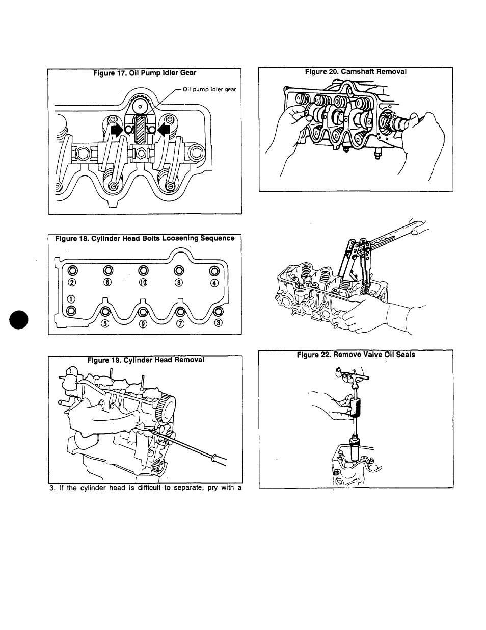
1. Remove timing belt (Section 2.2). Then, remove OIL PUMP
IDLER GEAR.
2. Remove the cylinder head. Loosen bolts in 2 or 3 stages,
in the sequence shown above.
screwdriver.
4. Remove the Camshaft (Figure 20).
5. Remove valve components parts (Figure 21).
6. Use a suitable puller to remove valve oil seals (Figure 22).
Checking Cylinder Head Distortion
Use a thickness gauge and a straightedge to measure
cylinder head distortion. See Figure 23 (next page). Lay the
Figure 21. Remove Valve Component Parts
straightedge across the cylinder head surface as shown.
Surface warpage must not exceed 0.004 inch (0.1 mm). If the
cylinder head exceeds the stated value, it must be replaced.
Resurfacing Limit: The amount of resurfacing that can be
done on the cylinder head depends on the amount of resur
facing on the cylinder block. If the amount of HEAD surfacing
is "A^and the amount of BLOCK surfacing is "B“, the maxi
mum limit is as follows:
Page 2.3-1