How to use table 11-12, Table 11-12. line sizing chart for liquid propane – Generac 86640 User Manual
Page 120
Attention! The text in this document has been recognized automatically. To view the original document, you can use the "Original mode".
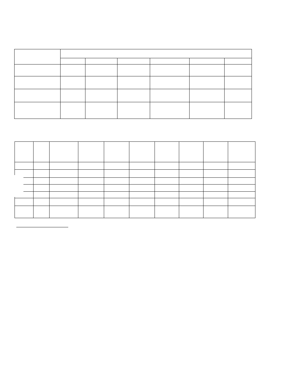
Table 11-11. Number of 20 Gallon Propane Cylinders Required at Various indicated
Temperatures when Kept at Least Half Full (Vapor Withdrawal Systems)
WITHDRAWAL RATE
LOWEST AVERAGE WINTER TEMPERATURE
32' F.
21TK
10 F.
ITTr
-10 F.
-20’ F.
1 0 C F H
(25,000 BTU/Hour)
1
1
1
1
1
2
25CFH
(62,500 BTU/Hour)
1
1
1
2
2
3
5 0 C F H
(125,000 BTU/Hour)
2
2
3
3
4
5
100 CFH
(250,000 BTU/Hour)
4
4
5
6
7
10
Table 11-12. Line Sizing Chart for Liquid Propane
LIQUID
GAS
FLOW
(CFH)
GAS
FLOW
(GPH)
1/4"
SCHEDULE
40 BO
3/8"
SCHEDULE
40 80
1/2“
SCHEDULE
40 80
PIF
3/4"
SCHEDULE
40 80
»E LENGTH
1"
SCHEDULE
40 80
N FEET
1-1/4“
SCHEDULE
40 80
1-1/2“
SCHEDULE
40 80
2“
SCHEDULE
40
360
10
729 16
540
15
324 185
720
20
182 104
825 521
|l440
40
46 26
205 129
745 504
2160
60
20 11
92 58
331 224
2880
80
11 6
51 32
187 127
735 537
3600
100
7 4
33 21
119 81
470 343
i
HOW TO USE TABLE 11-12:
1. Determine the required flow of UP gas required to run the generator at Its rated maximum capacity. Locate this flow in the left
hand column. If the flow falls between two numbers, use the larger number.
2. Determine the total length of piping from source to polrit of use.
3. Read across chart from left (Required Flow) to right, to find the total length of pipe which Is equal to or exceeds the distance
from source to point of use.
4. From this point, read up to find the correct pipe size.
Page 11-16