Cranking system description, Operational analysis, Engine control circuit board – Generac 86640 User Manual
Page 88: Start-stop switch, Description, Testing the switch, 10 amp circuit breaker, Starter contactor, Testing the starter contactor
Attention! The text in this document has been recognized automatically. To view the original document, you can use the "Original mode".
Section 9.3- ENGINE CRANKING SYSTEM
Cranking System Description
See Figure 7, below. Battery power is available to a
large terminal stud of the STARTER CONTACTOR. How
ever, the STARTER CONTACTOR contacts are normally-
open. From the STARTER CONTACTOR, battery voltage is
available to the ENGINE CONTROL circuit board, via Wire
13, a 10 amp CIRCUIT BREAKER, and Wire 15. Major
components of the engine cranking system include the fol
lowing:
D Engine control circuit board.
D
Start-Stop switch,
n 10 amp Circuit Breaker.
CD
Starter Contactor,
n Starter.
CD
12 volts Battery.
Figure 7. Engine Cranking System Diagram
Operational Analysis
Operation of the engine cranking system may be briefly
descrioed as follows (Figure 7):
1. Battery power is available to the STARTER CONTACTOR,
via the positive battery cable. Battery power is also available
to the ENGINE CONTROL circuit board, via Wire 13, a 10
amp CIRCUIT BREAKER, and Wire 15.
2. When the START-STOP SWITCH is set to “Start", Wire 17
and Pin 3 of the ENGINE CONTROL board are connected to
ground. Circuit board action then delivers 12 volts DC to the
STARTER CONTACTOR coil, via Wire 56. The STARTER
CONTACTOR is energized and its contacts close.
3. On closure of the STARTER CONTACTOR contacts, 12
volts DC is delivered to the STARTER. The engine cranks.
4. When the engine starts, the START-STOP SWITCH is
released and Wire 17 is no longer grounded. Circuit board
action opens the 12 volts DC circuit to Wire 56 and cranking
terminates.
Engine Control Circuit Board
See Section 9.4, "ENGINE CONTROL CIRCUIT.
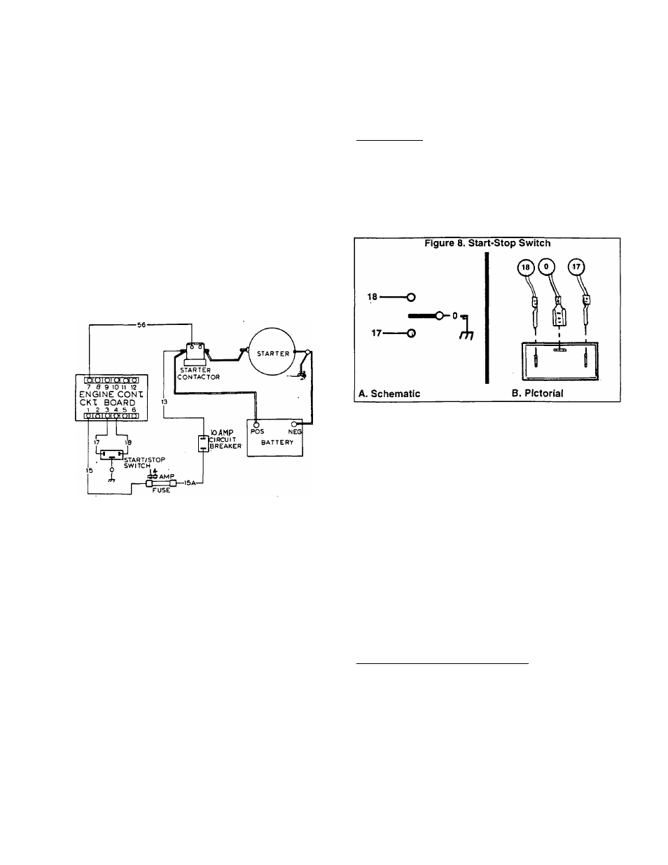
Start-Stop Switch
DESCRIPTION;
See Figure 8. Wires 17 (start), 18 (stop), and 0 (ground)
connect to the start-stop switch terminals.
Setting the switch to "Start" connects the Wire 17 circuit
to Wire 0 (ground). Engine control circuit board action then
initiates engine cranking and startup.
Setting the switch to "Stop" connects the Wire 18 circuit
to ground. The circuit board.then opens its circuit to Wire 14
and engine shutdown occurs.
TESTING THE SWITCH:
The start-stop switch can be tested using a volt-ohm-mil-
liammeter (VOM). Set the VOM to its "Rxl" scale and zero
the meter.
D Connect the VOM test leads across the Wire 17 and the
Wire 0 terminal of the switch. With switch at “Start", the
meter should read "continuity": at “Stop", switch should
read “infinity".
D Connect the VOM test leads across the Wire 18 and the
Wire 0 terminals of the switch. Set switch to “Start" and
meter should read “infinity". Set switch to “Stop" and it
should read “continuity”.
10 Amp Circuit Breaker
Refer to Section 9.4, "ENGINE CONTROL CIRCUIT.
Starter Contactor
DESCRIPTION:
The starter contactor (or starter solenoid) is attached to
the engine-generator control panel. See Figure 9.
TESTING THE STARTER CONTACTOR:
If the engine will not crank, the starter contactor can be
tested as follows:
1. Check for normal battery voltage at the large terminal stud
to which the positive battery cable connects.
a. If battery voltage is zero or low, check the battery cable
and the battery.
b. If normal battery voltage is read, go on to Step 2.
Page 9.3-1