Magnetic pickup – Generac 86640 User Manual
Page 78
Attention! The text in this document has been recognized automatically. To view the original document, you can use the "Original mode".
*
Electronic Governor Setup (Continued)
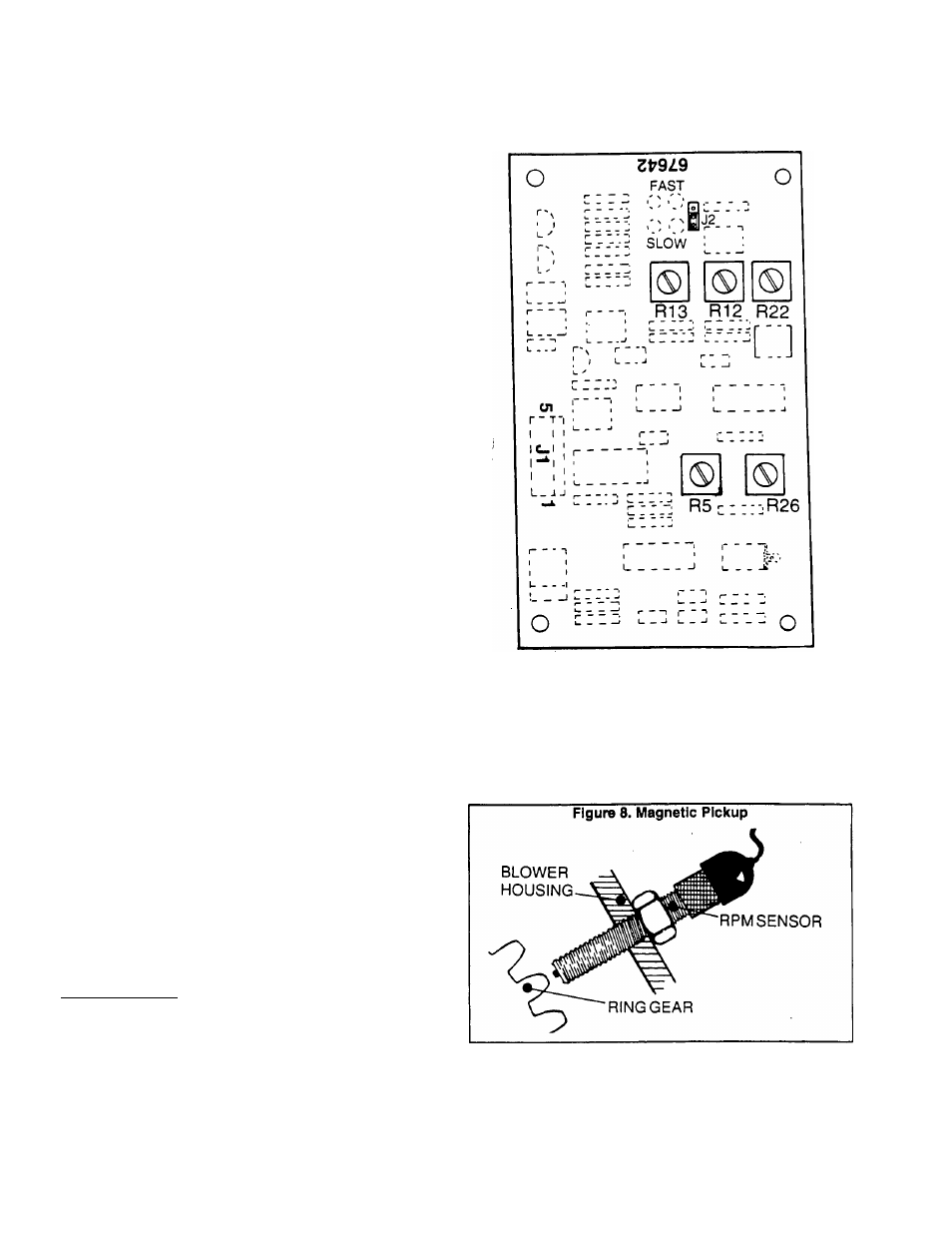
Set Jumper J2 to Its "FAST* position.
4. Adjust Speed Pot R5 clockwise to obtain the correct AC
frequency.
5. Check no-load stability. System stability can be improved
by adjusting R12 and R13 clockwise.
6. Apply 25 percent of the unifs rated load. Then, check
stability.
a. If undesireable oscillations are observed when the 25%
load is applied, adjust R22 clockwise.
b. Adjusting R22 clockwise will dampen undesireable os
cillations that occur when a load Is applied.
7. Shut the engine down. Then, restart it and observe startup
characteristics. If the overshoot that occurs during startup is
higher than desired, adjust R26 clockwise (to reduce startup
overshoot).
8. Apply rated block load to the generator. Observe the
recovery from block load application and from load dump.
a. Adjusting R12 and R13 counterclockwise will improve
recovery from block load application, but will tend to make
the system less stable.
b. Adjusting R26 counterclockwise will improve recovery
from load dump, but will allow more overshoot at startup.
Complete the preceding adjustments as required to ob
tain the best balance of all parameters. Basic guidelines for
system operation are as follows:
D
The system should reach stability at all load points with
not more than four (4) oscillations.
D The system should recover to within one (1) Hertz of
steady state in less than two (2) seconds for all load
transients.
CH No-load to full-load droop should be less than 0.5 Hertz
steady state.
Figure 7. Electronic Governor Control Circuit Board
Magnetic Pickup
The Magnetic Pickup is installed into a threaded hole in
the generator's blower housing and prevented from turning
by a stop nut. The tip of the pickup lies directly over the
flywheel’s ring gear teeth.
To install and properly set air gap, thread the pickup in
until its tip just contacts the ring gear. Then, back off about
1/2 to 3/4 turn and hold in that position while tightening the
stop nut.
CAUTION: DO NOT rotate the engine during the
above adjustment.________________________________
Page 7.2-2