Section 7.2- electronic governor, General, Lirj – Generac 86640 User Manual
Page 77: Governor actuator relay, Description, Testing, Governor actuator adjustment, Electronic governor setup
Attention! The text in this document has been recognized automatically. To view the original document, you can use the "Original mode".
Section 7.2- ELECTRONIC GOVERNOR
General
Some industrial mobile (IM) series generators may be
equipped with an electronic engine governor system. The
system consists of the following major components:
n A 12 volts DC Governor Actuator Relay (GAR).
■ n An Electronic Governor Actuator (EGA),
n An Electronic Governmor Control circuit board (EGC).
n A Magnetic Pickup assembly (MPU).
n Interconnecting wiring.
Figure 4 is an operating diagram of the electronic gover
nor system. Operation may be briefly described as follows:
1. During engine startup and running, an Engine Control
circuit board delivers 12 volts DC to a GOVERNOR ACTUA
TOR RELAY (GAR) via Wire No. 14. The Relay energizes
and its normally-open contacts close.
2. When the Relay contacts close, 12 volts DC is delivered to
the ELECTRONIC GOVERNOR CONTROL (EGC) circuit
board, to turn the governor system on.
3. Engine speed information is delivered to the ELECTRONIC
GOVERNOR CONTROL (EGC) circuit board from a MAG
NETIC PICKUP (MPU). This “actual* speed is electronically
compared to a "reference” speed that has been preset on the
circuit board.
4. If any difference exists between “actual" and "reference"
speed, the ELECTRONIC GOVERNOR CONTROL (EGC)
board sends speed correction signals to an ELECTRONIC
GOVERNOR ACTUATOR (EGA).
5. The ELECTRONIC GOVERNOR ACTUATOR (EGA) is
mechanically linked to the carburetor throttle valve.
Figure 4. Governor System Schematic
GOVERNOR
CIRCUIT
BOARD
1_ 5
4
3
2
1 _|
169
?
- 0 - n
166
79
I O-
LirJ
GOVERNOR
168 RELAY
-15
+12 VDC
rh
1-169
-TO GOVERNOR ACTUATOR
-79 —
FROM RPM SENSOR
Governor Actuator Relay
DESCRIPTION;
See Figure 5. The Relay is housed in the generator
control console. The Relay coil is energized when 12 volts
DC is applied at its Terminal A and the circuit is completed
through the coil to Terminal B and to ground.
TESTING:
To test the Relay, apply +12 volts DC to Relay Terminal
A and -12 volts DC to Terminal B. The Relay coil should
energize and normally-open Relay contacts 4 and 7 should
actuate closed.
With the Relay coil energized, a VOM connected across
Relay Terminals 4 and 7 should read “continuity“.
With the Relay coil de-energized, a VOM connected
across Relay Terminals 4 and 7 should read "infinity".
Figure 5. Governor Actuator Relay
COIL
NORMALLY-OPEN
CONTACTS
NORMALLY-CLOSED.
CONTACTS
A. Schematic
ysj
-nr
B. Pictorial
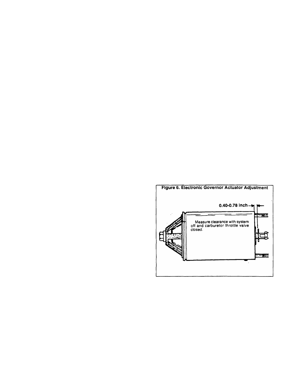
Governor Actuator Adjustment
With the engine shut down, adjust the length of the
Electronic Governor Actuator (EGA). With the carburetor
throttle valve closed, adjust so that approximately 0.40-0.78
inch (1-2mm1 of clearance exists between the EGA stop
washer and the EGA body. See Figure 6.
Electronic Governor Setup
The Electronic Governor Control (EGC) circuit board is
housed in the generator control console (see Figure 7). All
circuit board adjustments for new generators have been
completed at the factory and no additional adjustment should
be required. If the circuit board must be replaced, adjust the
governing parameters as follows:
1. See Figure 7. Set the speed pot (R5) fully counterclock-
wise.
2. Set all other potentiometers (R12, R13, R22, R26) to their
mid-point.
Page 7.2-1