Major components service data and specifications – Generac 86640 User Manual
Page 80
Attention! The text in this document has been recognized automatically. To view the original document, you can use the "Original mode".
Major Components
Service Data and Specifications
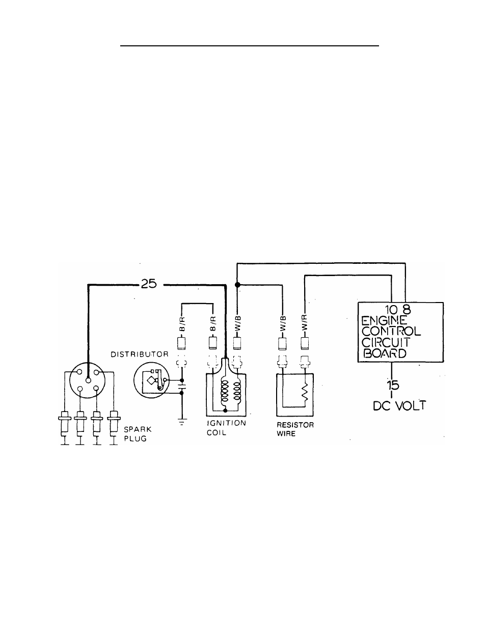
The engine ignition system consists of (af ignition coil,
(b) a distributor, (c) spark piugs, (d) spark plug leads, and (e) Firing Order......................................1-3-4-2
an ignition resistor.
Distributor Rotation .................Counterclockwise
Breaker Point Gap................... 0.018-0.022 inch
Distributor Cap insulation
Ignition System Operation
Resistance................................Greater than 50 meg-ohms
During engine cranking and running op^erations, an En-
Head Insulation
gine Control circuit board delivers 12 volts DC to the Ignition
cn
Coil primary winding via Wire No. 9. the coil primary winding
Resistance ... .......................... Greater than 50 meg-ohms
circuit is completed through the distributor breaker points and
Distributor Cap Carbon
to ground. Each time the distributor breaker points open, the
Point Length ............................ More than 0.012 inch
primary circuit is opened and a magnetic lield around the
(3mm) protruded length
primary coil winding collapses to induce a high voltage into ignition Coil Resistance
the ignition coil secondary winding. The high voltage from the
Primary Coll
1 3-1 5 ohms
coil secondary winding jumps the gap across the spark plugs.
_
^
^.................... ,
When the engine has started, only about 7-9 v^is .
Coll................8.7-11.7 k-ohms
required to maintain ignition. For that reason, once startup
sparK Plugs
bodcco
has occured, the Engine Control board terminates current
NGK...................................BPR6ES
flow to Wire No. 9 and delivers current flow to the ignition coil
CHAMPION....................... RN9YC
primary winding through a resistor wire (RW).
AC .....................................R42XLS
Spark Plug Gap ............... 0.031-0.035 Inch
Condenser Capacity .. .0.2-0.24 micro-farads
_________Section 8.1- GENERAL INFORMATION_________
Figure 1. Ignition System Diagram
Page 8.1-1