Section 4.4- optional remote radiator fan, Compartment fan, A remote radiator assembly – Generac 86640 User Manual
Page 56: Components, Operation, Figure 9. remote radiator fan operating diagram, 14 amp, Fuse
Attention! The text in this document has been recognized automatically. To view the original document, you can use the "Original mode".
Section 4.4- OPTIONAL REMOTE RADIATOR FAN
Some NP senes engine-generators are not equipped
with a unit-mounted radiator. The radiator on such units is
mounted at a remote location in the vehicle that houses the
generator. Such installations might require the following
options:
An electrically operated RADIATOR FAN, along with a
temperature sensor switch.
A squirrel cage type COMPARTMENT FAN which draws
cooling and ventilating air through the compartment housing
the generator.
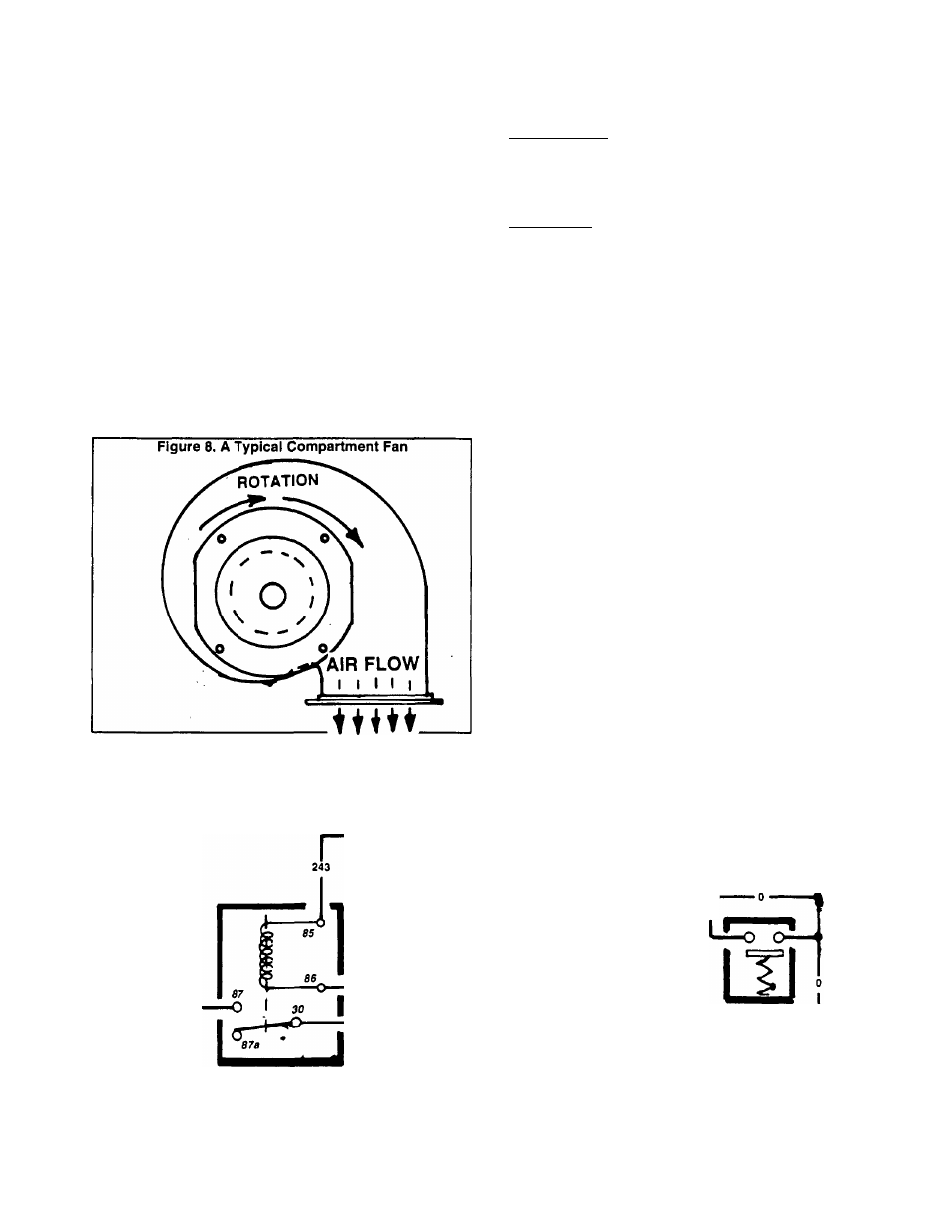
Compartment Fan
The compartment fan (Figure 8) must be properly lo
cated during installation. When running, it must draw cooling
and ventilating air through the generator compartment and
expel the air to the outdoors. The compartment fan is needed,
since an engine-driven fan Is not provided.
The compartment fan motor is connected to generator
AC output leads 11 and 22. When the generator is running
and AC voltage is available, the fan will operate.
A Remote Radiator Assembly
COMPONENTS:
Major components of a typical remote radiator and fan
include (a) the radiator, (b) the fan, (c) a thermostatic switch,
(d) mounting hardware, and (e) wiring harnesses. See Figure
10 on next page.
OPERATION:
See Figure 9, below. Battery voltage for fan operation is
always available to Tewrminal 30 of the Fan Relay (SR), via
a 14 amp fuse and Wire 13A. However, the fan relay normally-
open contacts are open and the fan Is NOT running. On
cranking and startup of the generator, an engine control
circuit board delivers 12 volts DC to the Thermostatic Switch
(TS) via Wire 14, Relay Coil, and Wire 243. If coolant temper
ature is below approximately 180' F., the thermostatic switch
contacts will be open. As soon as coolant temperature In
creases above 180' F., the switch contacts close and Wire
243 is grounded. Fan Relay (SR) then energizes, its normally-
open contacts close, and DC voltage is delivered to the FAN
via Wire 244. The fan is now powered and will run.
Figure 9. Remote Radiator Fan Operating Diagram
.244 .
^ 244
i
)
tt
L
FAN
RELAY
■ 13A .
NOTE: ThermottaUc switch contacts close above
2^3
^80"
F.; fan relay contacts are energised closed
when switch contacts close.
12VDC WITH
ENGINE RUNNING
"
only
,12 VDC FAN
POWER SUPPLY
- 14——
14 AMP
FUSE
THERMOSTATIC
7777777
Page 4.4-1