Stator ac power connection systems – Generac 86640 User Manual
Page 9
Attention! The text in this document has been recognized automatically. To view the original document, you can use the "Original mode".
NOTE: At the time thie Manual was written, all NP/IM
Series generators were equipped with the dual, 1-phasa
stator configuration. Some other possible stator config
urations will be mentioned here to cover future possibil
ities.
Stator AC Power Connection Systems
GENERAL:
Any one of several different connection systems are
used on NP and IM Series generators. Theses are(a) dual
1-phase, (b) 3-phase Delta, and (c) 3-phase Wye-Connected
systems.
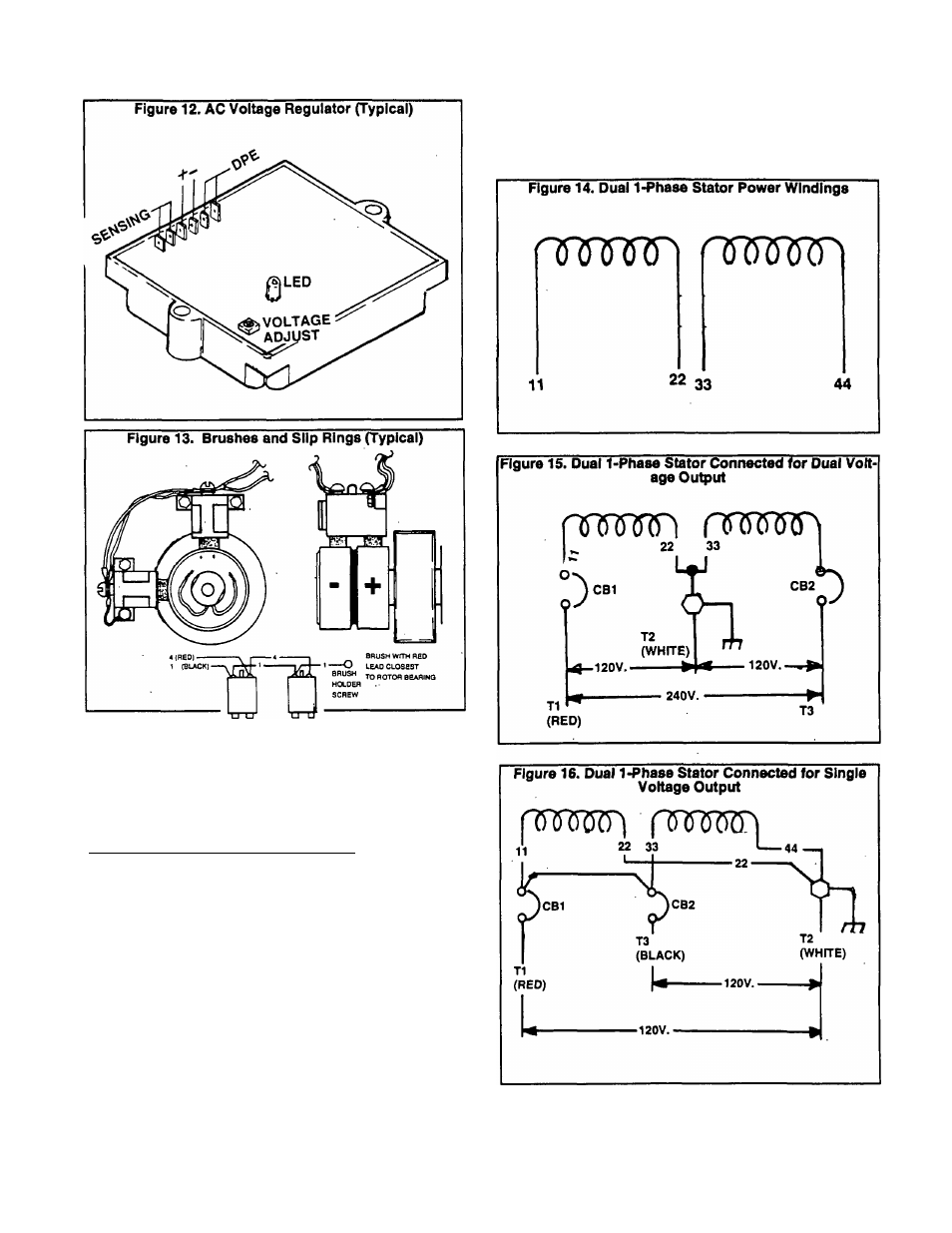
DUAL WINDING. 1-PHASE SYSTEM:
Figure 14 is a schematic representation of dual 1-phase
Stator AC power windings. Each Stator winding can supply a
120 volts AC output. When the two windings are connected
In series to form a 3-wire connection system, a 240 volts AC
output results.
Connected for Dual Voltage Output Some dual wind
ing systems may have been connected to provide a dual
voltage output (120 and/or 240 volts AC). See Figure 15.
Stator AC output leads 11 (T1) and 44 (T3) form the two hot
leads. The Junction of Stator leads 22 and 33 form the
"Neutral’ line (T2).
Connected for Single Voltage Output: If desired, the
Stator AC ou^ut leads can be reconnected for single voltage
output only (Figure 16). When this Is done, a jumper wire must
be connected between the two main circuit breakers (CB1
and CB2).
Page 1.1-5