General, Vapor withdrawal system, Liquid withdrawai system – Generac 86640 User Manual
Page 66: Figure 2. a typical vapor withdrawal system
Attention! The text in this document has been recognized automatically. To view the original document, you can use the "Original mode".
Section 6.1- INTRO. TO GASEOUS FUEL SYSTEMS
General
Some NP/IM series engine-generators may be equif^ed
with optional LP (liquefied petroleum) gas fuel systems. This
fuel is supplied as a liquid in pressure tanks.
LP gas is usually made up of (a) propane, (b) butane, or
(c) a mixture of the two gases. The liquefied fuel must be
converted to its vapor state before it enters the engine carbu
retor. Propane will vaporize at temperatures as low as 20' F.
(-6.7‘ C.). Butane exists in its liquid state when temperatures
drop below 32' F. (O’ C.). In colder weather, fuel suppliers will
usually increase the amount of propane in the fuel mixture for
better vaporization. Under extremely cold conditions, butane
gas may not provide sufficient vapor pressure to operate the
engine.
Q One gallon of butane liquid equals about 31.26 cubic feet
of butane gas.
EH
One gallon of propane equals about 36.39 cubic feet of
propane gas.
Vapor Withdrawal System
The LP gas fuel system may be either (a) a vapor
withdrawal system or (b) a liquid withdrawal system.
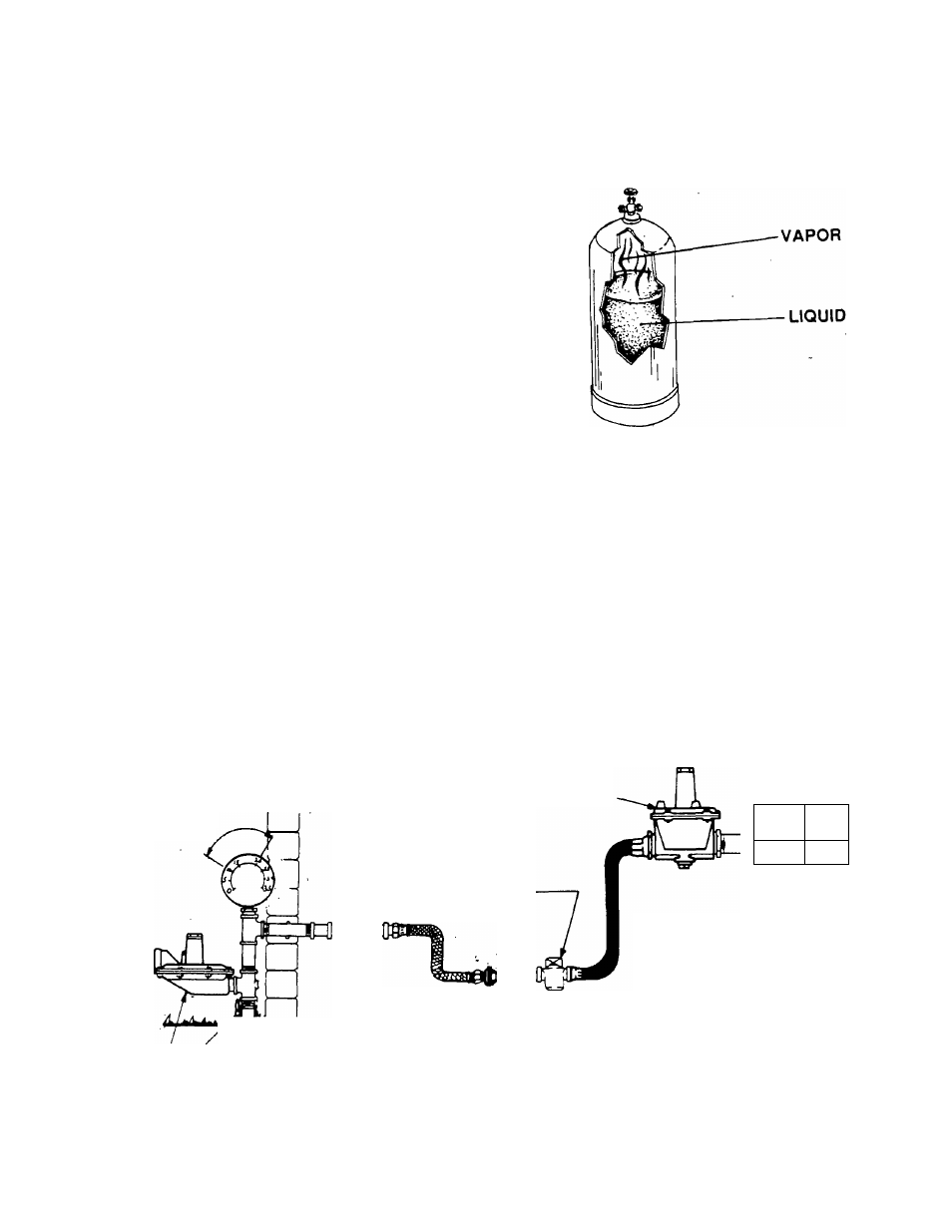
The vapor withdrawal system utilizes the vapors that
form above the liquid fuel in the supply tank. One typical
vapor withdrawal supply tank is shown in Figure 1.
The vapor withdrawal system, because it uses qaseous
fuel vapors. Is much like a natural gas system. See Figure 2.
The fuel vapors are delivered to a customer-supplied primary
regulator which reduces the gas vapor pressure. The gas
then goes to a fuel lockoff solenoid. Optimum gaseous pres
sure at the inlet to the fuel lockoff solenoid is about 11 inches
(water column) and not to exceed 14 inches (water column).
The function of the primary regulator is to provide this opti
mum fuel pressure to the solenoid. From the fuel lockoff
solenoid, the gaseous fuel is delivered to the inlet of a
pressure reducer valve. The pressure reducervalve receives
the gas at the stated optimum pressure, reduces the gas
pressure to a negative (vacuum) pressure of about -1 inch
(water column). The gas is then delivered to the carburetor
which meters the gas to the engine based on engine demand.
Figure 1. Typical Vapor Withdrawal Supply Tank
Liquid Withdrawai System
A typical liquid withdrawal fuel supply tank is shown in
Figure 3 (next page). A pickup tube extends down into the
tank. Vapor pressure on top of the fuel in the tank forces the
fuel to flow through the pickup tube and to the engine-gener
ator fuel system.
A typical liquid withdrawal type fuel system is shown in
Figure 4 on the next page. From the fuel supply tank, liquid
fuel flows to a fuel lockoff solenoid on the generator. The
liquid fuel Is then delivered to a vaporizer-regulator. Heated
engine coolant also flows through the vaporizer-regulator, to
heat the fuel and change it to its vapor state. The vaporized
fuel is then delivered to the engine carburetor at greatly
reduced pressure.
Figure 2. A Typical Vapor Withdrawal System
SECONDARY REGULATOR
11 In. H20
OPTIMUM
FUEL SHUTOFF VALVE
' r
br
r CARBURETOR-
I
? FROM SUPPLY TANK
PRIMARY REGULATOR
Page 6.1-1