Mission brownout lcd, Sleep – Maxim Integrated 71M6521BE Energy Meter IC Family Software User Manual
Page 97
71M652X Software User’s Guide
Revision 1.7
TERIDIAN Proprietary
97 of 138
© Copyright 2005-2007 TERIDIAN Semiconductor Corporation
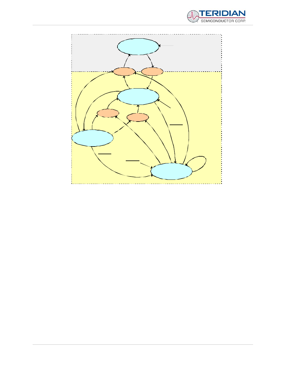
V3P3SYS
rises
V3P3SYS
falls
MISSION
BROWNOUT
LCD
SLEEP or
V1 > VBIAS
V1 <= VBIAS
LCD_ONLY
RESET &
VBAT_OK
RESET
IE_PLLRISE
-> 1
IE_PLLFALL
- > 1
IE_PB - > 1
IE_WAKE ->
1
PB
timer
timer
PB
RESET &
V3P3SYS
rises
V3P3SYS
rises
VBAT_OK
VBAT_OK
VBAT_OK
VBAT_OK
SLEEP
Figure 5-26: Operation Modes State Diagram
The wake-up timer is a little trickier to use than the pushbutton. To use it, one must first write the timer data, and then,
after a brief delay (about 32µs), enter LCD or sleep mode. The timer does not measure elapsed time. Instead, it counts
the RTC’s transitions. For example, if one programs a two minute delay at 00:00:30, the timer will actually wake the
chip at 00:02:00. Properly used, this is a feature, of course, but it can be surprising.
The wake-up timer, LCD and sleep modes are controlled by the bits in the WAKE register, XDATA address 0x20A9.
The lack of nonvolatile memory during the battery modes can be disconcerting at first. There are usually a few bytes
worth of available nonvolatile space in the unused LCD segment control bits in XDATA addresses 0x2036...0x2056.
The transition from mission mode to brownout and from brownout to mission mode is invisible to the code without
special care. First, there is a bit PLL_OK in the I/O RAM at address 0x2003 that reflects whether the phase locked loop
(PLL) is running or not. In order to save power, the PLL does not run when the part runs from any battery mode.
PLL_OK also drives logic that sets the bits IE_PLLRISE and IE_PLLFALL in IFLAGS, SFR E8. These are logically-ored
and routed to external interrupt 4, which is an edge-triggered interrupt. This interrupt could be called “the brownout
mode interrupt” because it signals any transition between brownout and mission mode. It is very important that both
IE_PLLFALL and IE_PLLRISE be cleared at the end of the interrupt, in the same instruction, otherwise the edge
needed for the next interrupt might fail to occur.
The brownout mode interrupt has to manage the transition to and from brownout mode. The Demo Code’s brownout
interrupt handles this by displaying a watt-hour value, and then performing a soft reset.
The chip starts a normal power-up in brownout mode, and then transitions to mission mode about 4.1 milliseconds after
power is applied. The code is often quite far along the brownout mode path at this point, and must gracefully transition
to mission mode. The soft reset in the brownout interrupt handles this requirement very well.
The Demo Code still includes a “belt and suspenders” test for a change to or from brownout mode in the main loop.
This also performs a soft reset.