Auto-calibration – Maxim Integrated 71M6521BE Energy Meter IC Family Software User Manual
Page 59
71M652X Software User’s Guide
Revision 1.7
TERIDIAN Proprietary
59 of 138
© Copyright 2005-2007 TERIDIAN Semiconductor Corporation
Auto-Calibration
The auto-calibration option (not compiled in the executable Demo Code) is a simplified calibration procedure based on
voltage, real energy and reactive energy measurements.
Before the calibration starts, the desired accumulation time (SCAL) and the applied (ideal) voltage and current have to
be entered by the user in the MPU memory locations VCAL and ICAL.
The procedure of this calibration method is the same as for the fast calibration procedure, as described in the DBUM:
The tangens of the ratio of VARh and Wh determines the phase angle. The ratio between applied (ideal) and measured
voltage determines the voltage gain. However, whereas the calibration spreadsheet uses extensive trigonometric
functions, the auto-calibration procedure implemented in the Demo Code utilizes much simpler mathematical
operations that are closer to the capabilities of the MPU.
As with the procedure presented in the DBUM, the target values should be applied to the meter and held constant
during the auto-calibration process.
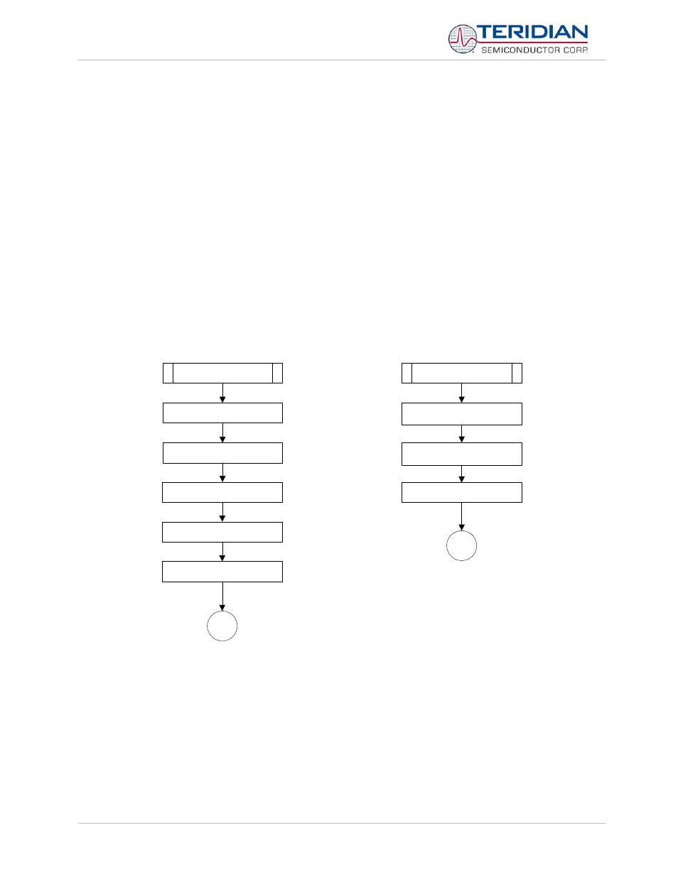
The routines shown in Figure 5-14 show how the auto-calibration is started. The cal_begin() routine starts a state-
machine by setting the flag cal_flag to YES, after setting the calibration factors to default values, recording the
calibration temperature, calculating the temperature compensation coefficients and setting the counter cs for calibration
cycles.
The actual stabilization delay, measurement and adjustment phases are managed by separate routines that are
activated by cal_flag being YES and controlled by the variable cs which counts down accumulation intervals.
cal_begin()
END
set calibration values to unity
record calibration
temperature
start count down sequence
calculate PPMC and PPMC2
and write to CE
cal_flag = YES
set calibration values to
unity
END
copy table of starting values
to CE data area
calculate PPMC and PPMC2
and write to CE
populate table with unity
values
Figure 5-14: Auto-Calibration
The processing of the calibration steps is performed by the routine calibration(), which is called in ce_update() when
new data becomes available, i.e. once per accumulation interval. The auto-calibration mechanism functions as a state-
machine, sequenced by the variable “cs”, which is used to count down accumulation intervals:
1) If cs > Scal: The state machine waits for the CE to settle after the unity gain and temperature
compensation data are loaded in the routine cal_begin().
2) If cs = Scal: The variables for each cumulative voltage and current measurement are cleared.